What Is STM32? A Beginner’s Guide
If you’ve spent any time around electronics forums or embedded systems job listings, you’ve probably seen the term STM32 come up more than once. It’s in blinking LED tutorials, drone builds, 3D printer boards, industrial equipment, basically everywhere. But if you’re just getting started, the term itself doesn’t really explain anything. Is it a chip? A brand name? A type of development board?
It’s not complicated once you understand it properly, which is what this guide is for. By the time you finish reading, you’ll know what STM32 actually is, what’s going on inside these chips, and how to get a real program running on real hardware.
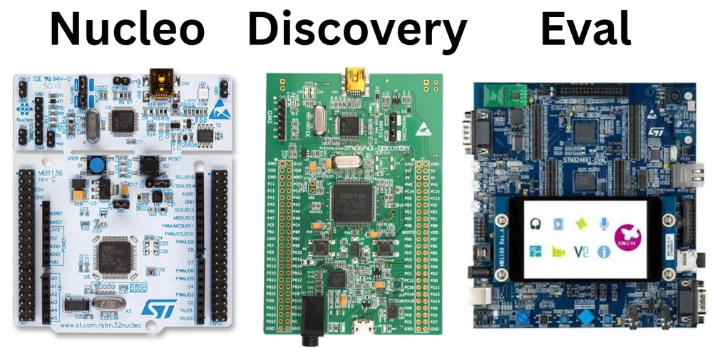
Table of contents
What Is a Microcontroller?
Before getting into STM32 itself, it helps to understand what a microcontroller actually is.
A microcontroller is a tiny computer built onto a single chip. Your laptop’s processor needs separate RAM sticks, a storage drive, and other supporting hardware around it just to function. A microcontroller does not work that way. It packs the processor, memory, and input and output pins into one small package, and it is built to do one job, or a few closely related jobs, reliably, often for years without a restart.
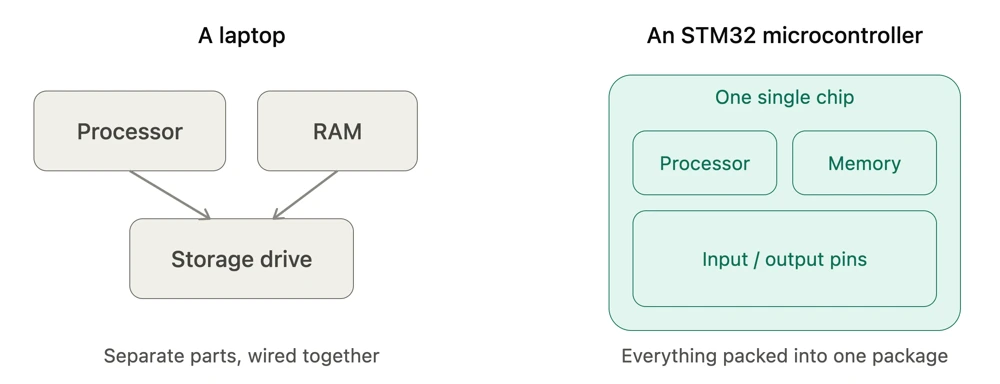
This is a big part of what makes microcontrollers so different from the computers most people are used to. There’s no operating system booting up, no background apps competing for resources, and no waiting around for anything to load. The chip powers on, starts running its one program, and keeps running it until the power is cut off. That simplicity is exactly why microcontrollers show up in places where reliability matters more than raw computing power.
You’ll find microcontrollers quietly running inside things you use every day. A washing machine uses one to control its wash cycles and motor speed. A car dashboard uses one to read sensors and show your speed and fuel level. Coffee makers, drones, and medical monitors all work the same way: one small chip doing one thing well, over and over.
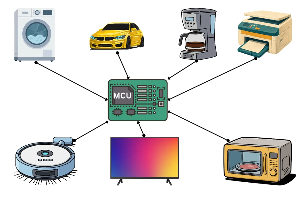
What ties all of these examples together is scale and cost. A microcontroller can cost less than a cup of coffee, run on a battery for months or even years, and still get the job done without needing anyone to babysit it. That combination of being cheap, low power, and dependable is why they end up buried inside so many products without anyone thinking twice about them.
A microcontroller isn’t built to handle everything you throw at it. It’s built to do one job, and do it the same way, correctly, every single time.
What Is STM32?
STM32 is a family of microcontrollers made by STMicroelectronics, a European semiconductor company. It is not one chip. It is a large product line covering hundreds of individual microcontroller models, all built around processor cores licensed from Arm, specifically the Cortex-M series.
That shared core matters. Learn to program one STM32 chip, and most of what you know carries over to the next one, and often to microcontrollers from other manufacturers that also use Arm cores.
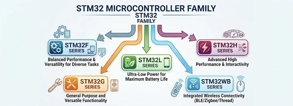
STM32 chips are split into series, and each one is built for a different kind of job:
| Series | Built For |
|---|---|
| STM32F | General-purpose projects, most common starting point |
| STM32L | Ultra-low power, ideal for battery-powered devices |
| STM32H | High performance, heavy processing tasks |
| STM32G | Cost-sensitive, mainstream applications |
| STM32WB | Wireless connectivity, Bluetooth-enabled projects |
This range is a big part of why STM32 has become so widely used. A simple soil moisture sensor and a complex robotics controller can both be built on STM32, just on different chips within the family.
What Is Inside an STM32 Microcontroller?
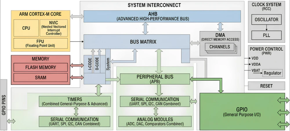
Every STM32 chip is built from the same handful of parts, and once you know what they are, a datasheet stops looking so intimidating.
At the centre sits the processor core, which runs your program’s instructions one after another. Around it are two kinds of memory. Flash memory stores your compiled program permanently, so it survives even after the power is switched off. RAM holds working data while the program runs, and it clears itself the moment power is lost.
Beyond the core and memory, the peripherals are where most of the real work happens. A peripheral is a small piece of built-in hardware that handles one specific job, so the processor doesn’t have to manage every tiny detail itself. Some of the most common ones:
- Timer – measures time intervals and generates precise pulses
- UART – sends and receives data with other devices
- ADC – converts analog sensor signals into digital values
- SPI and I2C – connect to sensors, displays, and memory chips
- DMA – moves data between memory and peripherals on its own, without tying up the processor
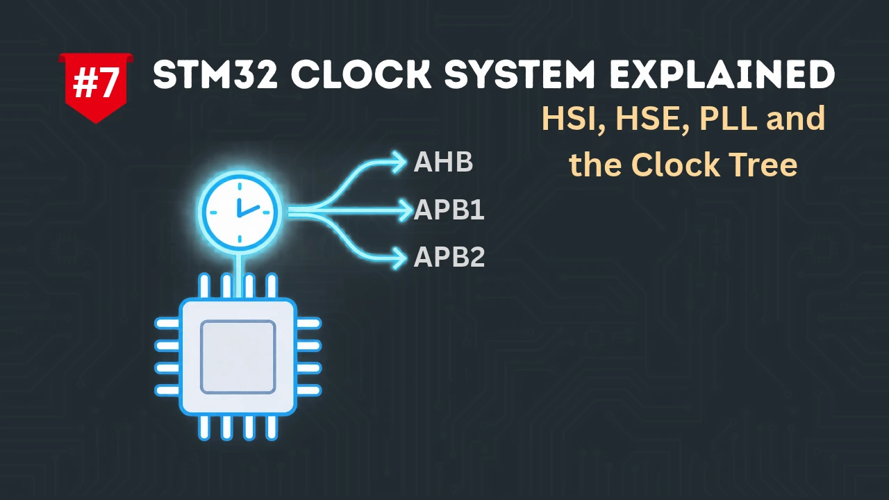
Finally, there’s the clock system, which generates the timing signals everything else in the chip depends on. Configuring it properly is a more advanced topic, and we’ll cover soon in our STM32 series.
How Does an STM32 Program Run?
Programming a microcontroller is different from building a website or a mobile app. There’s no operating system running quietly in the background, at least not in most beginner projects. Your code talks almost directly to the hardware.
You write your program, usually in a language called C, describing exactly what the chip should do. A compiler translates that code into instructions the processor can run. Then a small hardware tool, called a programmer or debugger, transfers those instructions onto the chip’s flash memory. This step has its own name in the embedded world: flashing.
Once the chip powers on, the processor starts reading instructions from a fixed point in flash memory. Most programs run a short setup section first, where pins and peripherals get configured, and then settle into a loop that repeats for as long as the chip has power. Inside that loop, your code might check a sensor, update a display, or flip a pin on and off to blink an LED.
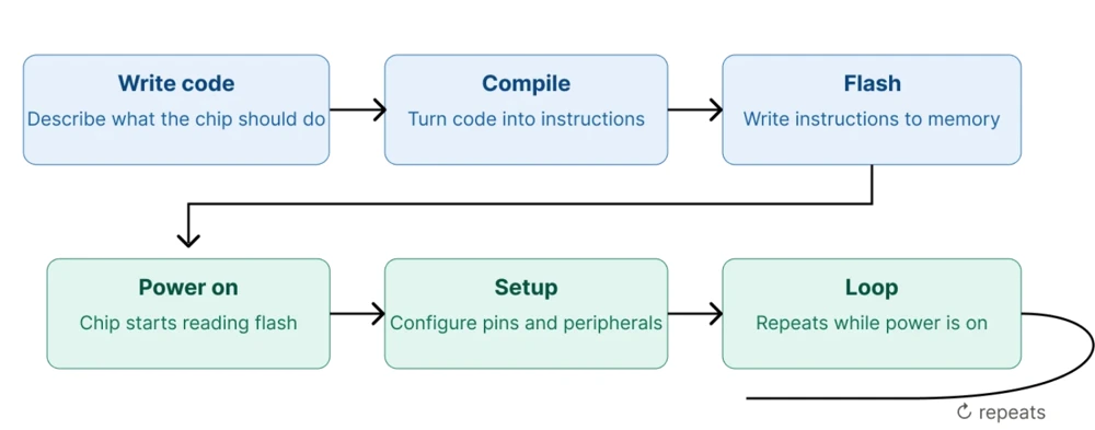
There are very few layers between your instructions and the actual hardware here, which is why microcontroller programming feels more direct once you get past your first project.
What Do You Need to Start STM32 Development?
Getting started doesn’t take a big investment or a cluttered workbench. Here’s what you actually need:
- An STM32 development board, with Nucleo or Discovery boards being the easiest starting point
- A USB cable to connect the board to your computer
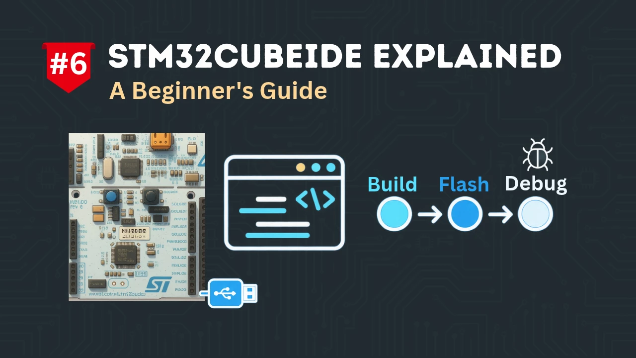
- STM32CubeIDE, a free development tool from STMicroelectronics
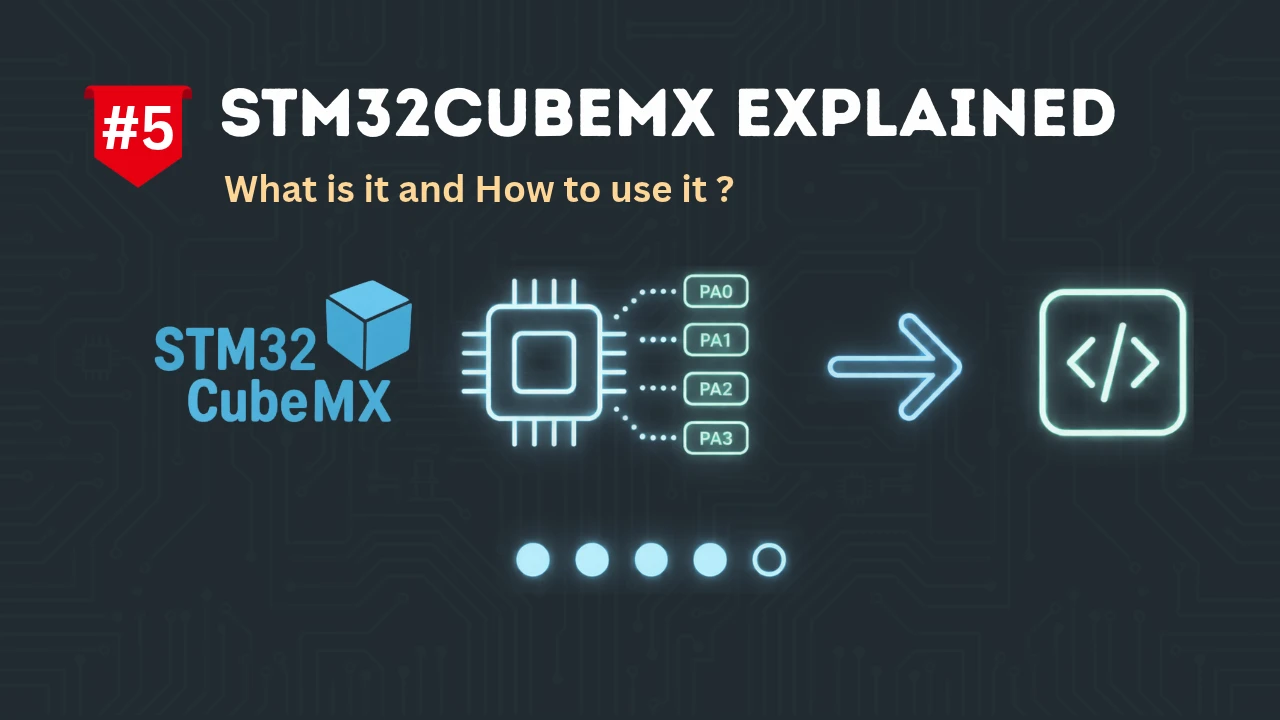
- STM32CubeMX, a free configuration tool also from STMicroelectronics
- Optionally, a small breadboard, some jumper wires, and a few basic parts like LEDs, resistors, and push buttons
Nucleo and Discovery boards are worth calling out because they include a built-in programmer. Plug in one USB cable, and you’re ready to flash code, with nothing extra to buy or set up. For this guide, we’ll be using the NUCLEO-F446RE as our reference board.
STM32CubeMX is where the graphical pin configuration happens. It lets you set up pins, peripherals, and the clock by clicking through a visual interface instead of digging through a datasheet. Once you’re done configuring, CubeMX generates a project you can open directly in STM32CubeIDE, where you write your actual code, then build and flash it to the board.
Your First STM32 Development Workflow
Let’s build something real: the classic blinking LED project. It’s simple, but it touches every idea covered so far, and it’s the same starting point almost every STM32 developer has used at some point.
We’ll use STM32CubeMX to set things up and STM32CubeIDE to write and flash the code. Here’s the workflow at a glance:
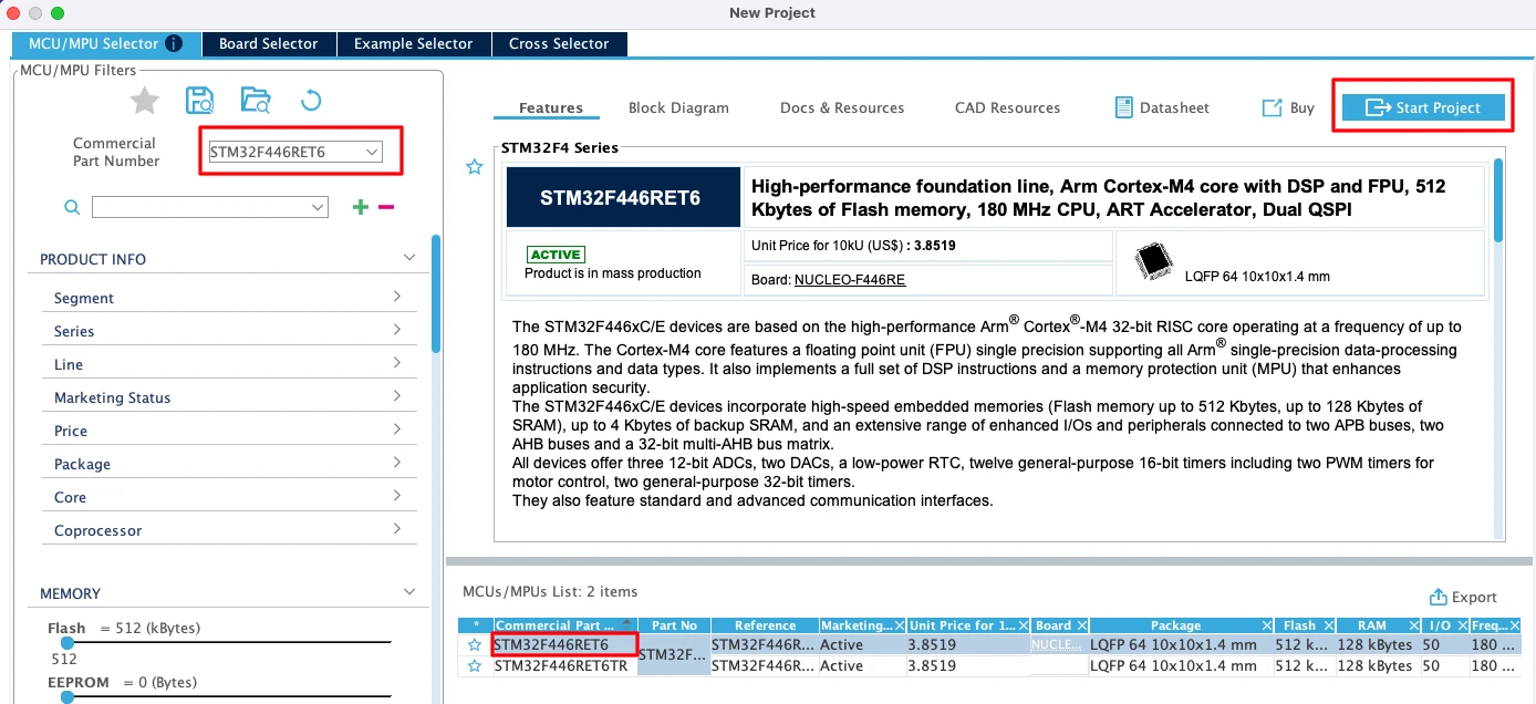
- Open STM32CubeMX and select your MCU. We’re using the STM32F446RE here, the chip on the Nucleo-F446RE board, but the steps are nearly identical for other boards.
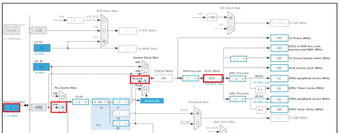
- Configure the system clock. Every STM32 board needs its clock set up correctly before anything else will run properly. We’ll cover this in detail in a separate tutorial, since it changes slightly depending on which board you’re using.
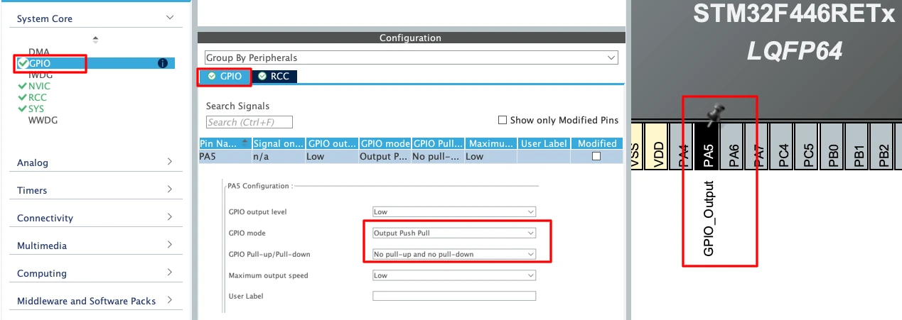
- Set your LED pin as a GPIO output. On the Nucleo-F446RE, the onboard LED sits on pin PA5.
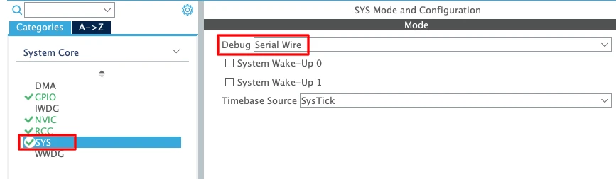
- Enable Serial Wire Debug under SYS settings, so the ST-Link can actually flash and talk to the board.
- Generate the project and open it in STM32CubeIDE.

- Write a few lines inside the main loop using HAL_GPIO_TogglePin() paired with HAL_Delay(), which flips the LED state on and off at a fixed interval.
|
1 2 3 4 5 6 7 |
while (1) { /* USER CODE BEGIN 3 */ HAL_GPIO_TogglePin(GPIOA, GPIO_PIN_5); HAL_Delay(1000); /* USER CODE END 3 */ } |
- Build the project, flash it to your board, and watch the LED blink.
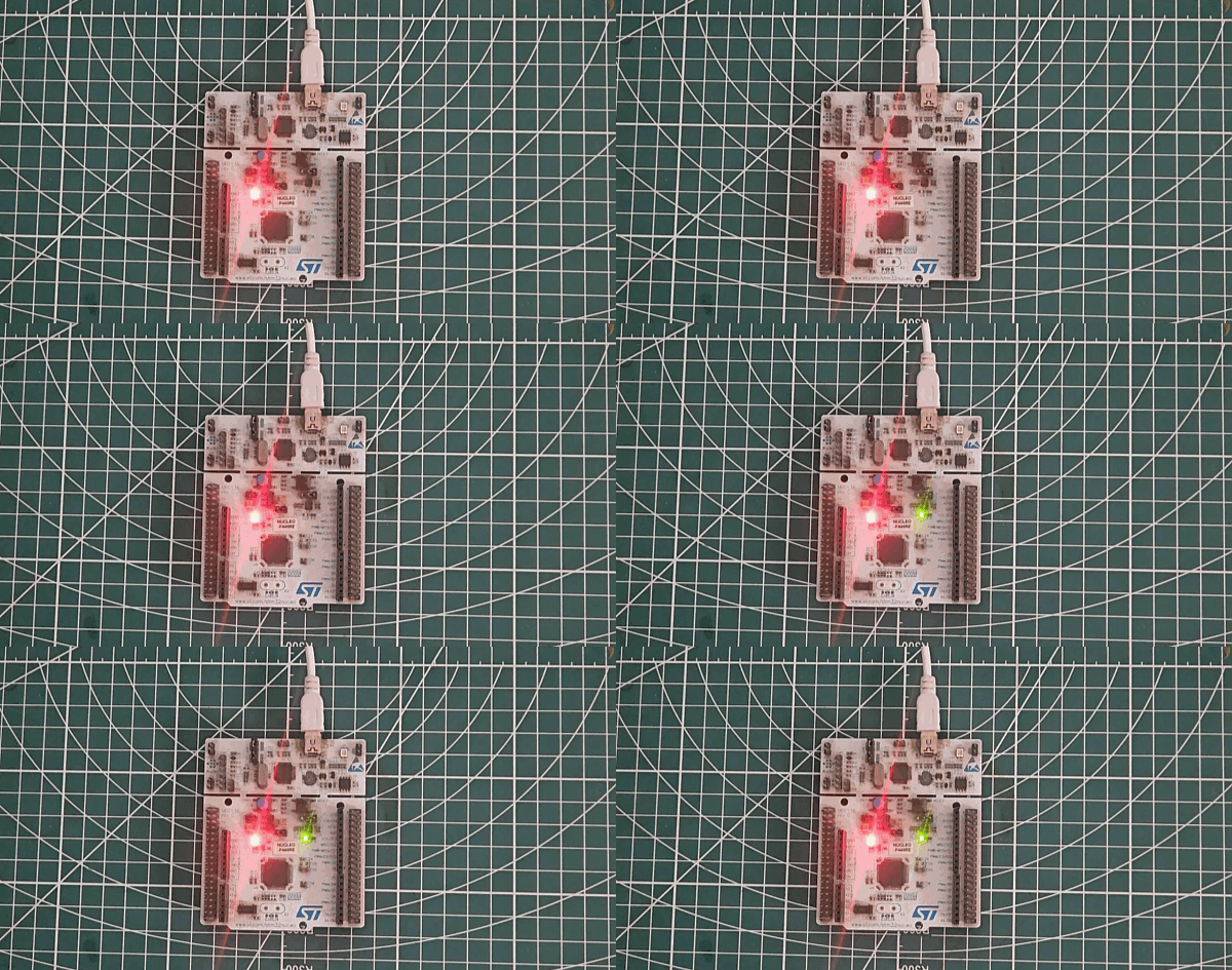
That’s the whole cycle: configure, generate, write, build, flash, run. Every bigger STM32 project you build later, whether it reads a sensor or drives a motor, follows this same pattern underneath.
To save you from starting with a blank project file, a complete, ready-to-open blinking LED project is available for download alongside this article. Open it in STM32CubeIDE, build it, flash it, and watch it run on your own board.
Where to Go Next
Blinking an LED looks small on paper, but it’s your first full lap through the STM32 development process: code, compile, flash, and watch real hardware respond. Every project after this one, no matter how advanced, is built on that same loop.
From here, a good next step is reading input from a push button, since it gets the chip reacting to the outside world instead of just controlling it. After that, timers let you handle timing more precisely than a simple delay ever could, and UART lets your board send messages back to your computer, which is a big help once you start debugging bigger programs. Once those feel comfortable, reading a sensor over I2C and controlling a motor with PWM are natural next steps.
Download the Project Here
Download the CubeMX project files and HAL source code — all tested on real hardware.
If you find this useful, you can support us with a Donation as well.