STM32 Timers Complete Guide
STM32 timers are the main tool for anything that involves time in an STM32 program. In the earlier GPIO articles, the time was handled in a very simple way. The program waited with HAL_Delay(), or it read a pin again and again, and the CPU stayed busy for the whole waiting time. This approach works for a blinking LED, but it does not work for a real product. A program that has to read a sensor every millisecond, generate a motor signal, and answer a button press at the same time cannot do all three with delay loops.
A hardware timer solves this problem. It is a counter that runs alongside the CPU, counts clock pulses on its own, and reports the result through an interrupt, an output pin, or a trigger signal for another peripheral. The CPU only configures the timer once and then continues with other work. This is the first article of the timer series, and it works as an overview that introduces the ideas the later articles build on.
In this article, we will begin with what a hardware timer is and how it differs from a software delay. Then we will look at the tasks a timer can perform and the three timer types of the STM32 family. After that, we will follow the path of the clock signal through the prescaler, the counter, and the auto-reload register, and we will see how an update event is created. In the later sections, we will cover a short overview of the operating modes, configure a periodic timer interrupt in STM32CubeMX, and finish with a learning path for the rest of the series.
The examples in this article use the STM32F4 series and the HAL library, with the NUCLEO-F446RE board as the reference. The timer instances and some of their features differ between STM32 families and between individual devices, and these differences are marked where they matter. This article is part of the STM32 timer tutorial series.
Table of contents
What Are STM32 Timers
A hardware timer is a peripheral that contains a counter register and a circuit that increases this counter on every pulse of a clock signal. The counter runs independently of the CPU, so it keeps counting while the program executes other instructions, waits in a sleep mode, or handles another interrupt. Because the clock frequency is known, the value of the counter can be converted directly into time, and the timer can be configured to act when the counter reaches a chosen value.
This makes a timer useful for any task that depends on exact timing. Typical examples are: a periodic task that must run every few milliseconds, a PWM signal that dims an LED or drives a motor, a measurement of the width of an incoming pulse, and the position reading of a rotary encoder. All of these tasks can be done by software, but the timing of a software solution depends on what the CPU is doing at that moment, while the timing of a timer depends only on its clock.
Hardware Timers vs Delay Loops
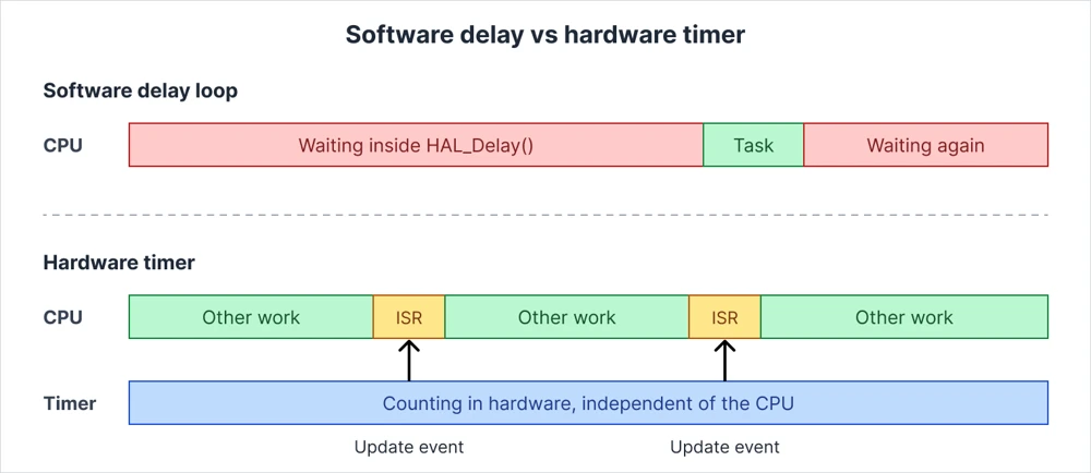
A software delay keeps the CPU occupied. A function such as HAL_Delay() blocks the program until the requested time has passed, and a simple counting loop does the same thing in a less accurate way. During this time, the CPU cannot read a sensor, update a display, or respond to a communication request unless the code is restructured around the delay. The accuracy of a counting loop also depends on the compiler settings, the clock speed, and any interrupts that happen to run during the loop.
A hardware timer reverses this arrangement. The timer counts in hardware, and the CPU is informed only when the selected time has passed. The diagram below shows how the two approaches use the processor.
| Software delay loop | Hardware timer |
|---|---|
| The CPU waits and does nothing else | The CPU continues with other work |
| Accuracy depends on code and interrupts | Accuracy depends only on the timer clock |
| Simple for a single short pause | Needed for periodic and parallel tasks |
| Cannot generate PWM or measure pulses well | Can generate and measure signals in hardware |
A software delay is still a sensible choice for a short pause during startup, for example when a sensor needs a few milliseconds before its first reading. For everything that repeats, runs in parallel with other tasks, or needs a precise timing relationship with a signal on a pin, a hardware timer is the correct tool.
STM32 Timer Uses
The same counter hardware supports many different functions, and the sections below give a short overview of each. Every function has a dedicated article later in the series.
Generate Accurate Time Delays and Periodic Events
The most common use of a timer is to raise an interrupt at a fixed interval, for example every millisecond or once per second. The interval depends only on the timer clock and on two register values, so it stays the same even when the main program becomes busier. This is the basis for sampling a sensor at a regular rate, running a control loop, handling timeouts, and building a small task scheduler. A timer can also replace the delay in the debounce state machine that was described in the GPIO interrupts article. The details are covered in the STM32 timer interrupt article.
Generate PWM Signals
Pulse width modulation switches an output pin on and off at a fixed frequency while the share of time spent in the on state is controlled. A timer produces this signal entirely in hardware, so the CPU only writes a new compare value when the duty cycle has to change. PWM is used for dimming LEDs, driving DC motors, controlling servos, and producing simple tones with a buzzer. Timer channels that output PWM are connected to pins through the alternate functions described in the alternate function article. The STM32 PWM article explains the setup in detail.
Measure External Signals
A timer can also work in the opposite direction and measure a signal that arrives on a pin. In input capture mode, the timer copies the counter value into a register at the moment an edge arrives. The difference between two captured values gives the period or the pulse width in timer ticks, and this can be converted into a frequency or a time. Typical uses are measuring the echo pulse of an ultrasonic sensor, reading the signal of an RC receiver, and finding the frequency of a square wave. This topic is covered in the input capture article.
Count Pulses and Read Encoders
A timer does not have to count its own clock. In external clock mode, it counts pulses that arrive on a pin, which makes it a hardware pulse counter that can follow signals faster than a polling loop or an EXTI interrupt could handle. Many STM32 timers also contain an encoder interface that reads the two signals of a quadrature encoder and counts up or down depending on the direction of rotation. The counter value then represents the position of the shaft, and the CPU can read it at any time. The encoder mode article shows the complete setup.
Synchronize Peripherals and Trigger ADC Conversions
Timers can also work as a clock source for other parts of the microcontroller. A timer can send a trigger output signal, called TRGO, that starts an ADC conversion at an exact interval, updates a DAC, or starts another timer. This gives a uniform sampling rate without any CPU involvement, which is important for audio, measurement, and control applications. One timer can also act as a master and another as a slave, so that several outputs start together or follow each other with a fixed delay. These features are described in the timer synchronization article.
Types of STM32 Timers
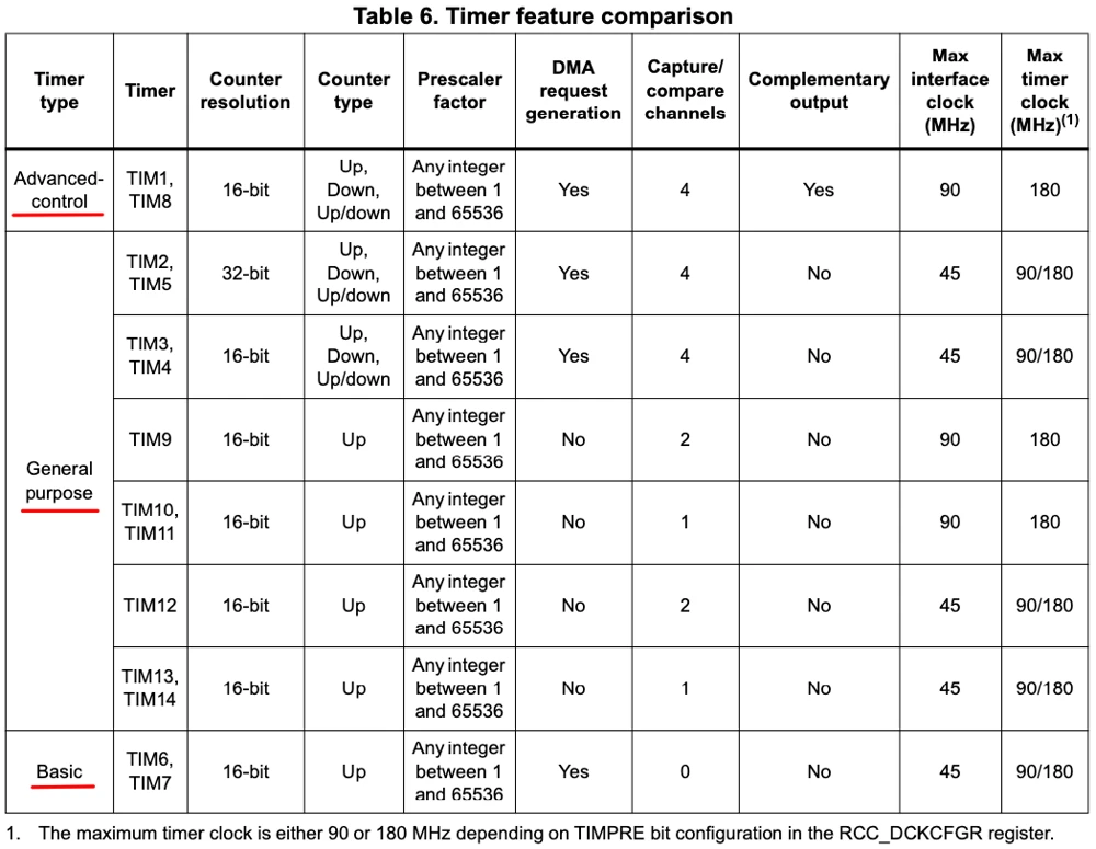
The STM32 family contains three main groups of timers, which are called basic, general-purpose, and advanced-control timers. They all use the same counting principle, and the groups differ in how many features are placed around the counter. A basic timer contains only the counter and its update event. A general-purpose timer adds capture and compare channels, and an advanced-control timer adds the extra circuits needed for motor control and power conversion.
| Type | Examples on STM32F446 | Counter width | Main features |
|---|---|---|---|
| Basic | TIM6, TIM7 | 16-bit | Time base, update interrupt, trigger output for DAC and ADC |
| General-purpose | TIM2 to TIM5, TIM9 to TIM14 | 16-bit (TIM2 and TIM5: 32-bit) | PWM, input capture, output compare, one-pulse mode, encoder interface (TIM2 to TIM5) |
| Advanced-control | TIM1, TIM8 | 16-bit | Everything in general-purpose timers, plus complementary outputs, dead time, break input, repetition counter |
- Basic timers are the simplest option when only a time base is needed. They have no channels and no pins, so they cannot generate PWM or capture a signal, but they can create periodic interrupts and trigger the DAC or ADC.
- General-purpose timers are the most common choice because they support almost every function that was described in the previous section. On the STM32F4 series, the timers TIM2 to TIM5 are the full-featured ones, with four channels each. The timers TIM9 to TIM14 are simplified versions with one or two channels and an up-counting counter only. The 32-bit counters of TIM2 and TIM5 are useful for measuring long intervals at a high resolution without handling a counter overflow.
- Advanced-control timers are designed for driving power stages such as half bridges and three-phase inverters. Their main additions are complementary outputs with programmable dead time, a break input that can switch off the outputs immediately in case of a fault, and a repetition counter that delays the update event. These features are covered in the advanced-control timer article.
The number of timer instances and the features of each one depend on the microcontroller. A small device such as an STM32G0 offers only a handful of timers, while a large device can contain more than a dozen. Some families also include timers that are not part of these three groups, for example low-power timers that keep running in the stop mode, and high-resolution timers in a few devices. The datasheet shows which timers a device contains, and the reference manual describes the registers of each one. The pin assignment of the timer channels can be checked in the pinout view of CubeMX.
How an STM32 Timer Works
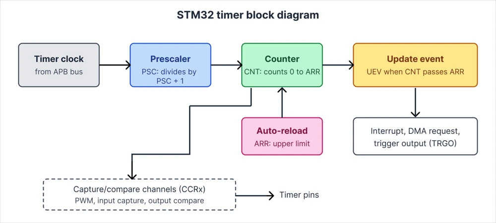
All STM32 timers share the same core structure. A clock signal enters the timer, a prescaler divides it, and a counter counts the divided pulses. When the counter reaches a limit that is stored in the auto-reload register, the timer creates an update event and restarts the count. The diagram below shows this path from the clock source to the outputs.
Timer Clock
Every timer receives its clock from the peripheral bus it is attached to. On the STM32F4 series, the timers TIM2 to TIM7 and TIM12 to TIM14 are on the APB1 bus, and the timers TIM1, TIM8, TIM9, TIM10, and TIM11 are on the APB2 bus. The timer clock is not always equal to the bus clock. When the APB prescaler is set to 1, the timer clock equals the bus clock, and for any other prescaler value the timer clock is twice the bus clock.
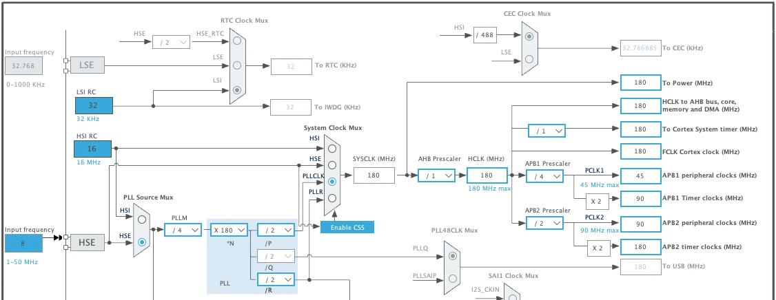
On a NUCLEO-F446RE that runs at 180 MHz, with the APB1 prescaler set to 4 and the APB2 prescaler set to 2, the timers on both buses receive a clock of 90 MHz and 180 MHz respectively. The STM32 clock system article explains how these bus frequencies are created, and the Clock Configuration tab of CubeMX displays the timer clock values directly.
Prescaler (PSC)
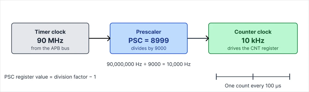
The prescaler divides the timer clock before it reaches the counter. The value that is written into the PSC register is one less than the real division factor, so a PSC value of 8999 divides the clock by 9000. A 90 MHz timer clock with this prescaler gives a counter clock of 10 kHz, which means that the counter increases once every 100 microseconds. The prescaler makes it possible to slow down a fast timer clock so that long time intervals fit into the limited range of a 16-bit counter.
Counter (CNT) and Auto-Reload Register (ARR)
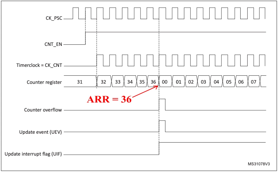
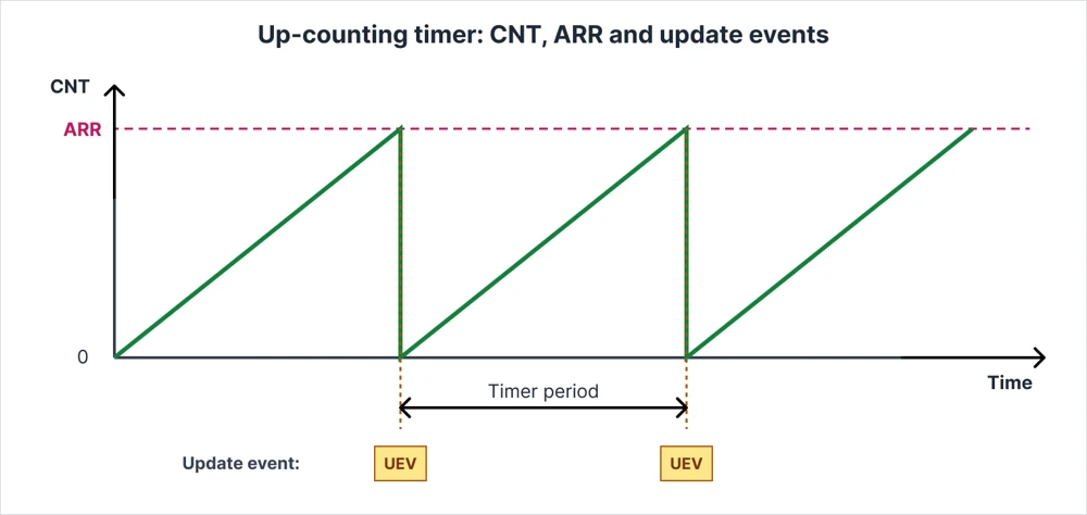
The counter register CNT holds the current count, and it increases on every pulse of the divided clock. The auto-reload register ARR holds the upper limit. In the default up-counting mode, the counter starts at zero and counts until it reaches the value of ARR. On the next clock pulse, it returns to zero and the cycle starts again. A counter that counts from zero to ARR takes ARR + 1 steps for one full cycle.
Update Event and Timer Period
The moment at which the counter returns to zero is called the update event. At this point, the timer sets the update flag in its status register, and it can raise an interrupt, send a DMA request, or create a trigger output signal for another peripheral, depending on the configuration. The time between two update events is the timer period, and it follows from the clock and the two register values.
The update frequency is calculated as the timer clock divided by the product of (PSC + 1) and (ARR + 1). With a timer clock of 90 MHz, a PSC of 8999, and an ARR of 9999, the result is 90,000,000 divided by 9000 and then by 10,000, which gives exactly 1 Hz. The timer therefore creates one update event every second.
The auto-reload register can be buffered with a preload feature. When the preload is enabled, a new ARR value that is written during operation takes effect at the next update event, which prevents a timer cycle from being cut short or stretched. CubeMX exposes this feature as the auto-reload preload setting.
STM32 Timer Operating Modes
The same counter structure can be used in several operating modes, and each mode connects the counter to the outside world in a different way. The sections below give a short introduction to each one. The dedicated articles in the series describe the registers, the CubeMX settings, and a working example for each mode.
Time-Base and Interrupt Mode
In the time-base mode, the timer only counts and creates update events. The update event raises an interrupt, and the application code in the callback runs at a fixed interval. This is the simplest mode and the starting point of the series. It is covered in the STM32 timer interrupt article.
PWM Output
In the PWM mode, a capture/compare register defines the point within the period at which an output pin changes its level. The auto-reload register and the prescaler set the frequency, and the compare value sets the duty cycle. The PWM article explains how to generate signals for LEDs, motors, and servos.
Input Capture
In the input capture mode, an edge on a timer pin stores the current counter value in a capture register. Two consecutive captures give the period or the pulse width of the signal, which makes this mode the main method for measuring frequencies and pulse lengths. It is described in the input capture article.
Output Compare
In the output compare mode, the timer changes the state of a pin or raises an interrupt when the counter matches a compare value. This allows the generation of precisely timed single edges and of signals with several different delays from one counter. The output compare article shows the available output actions.
One-Pulse Mode
In the one-pulse mode, the timer produces a single pulse of a defined delay and width after a trigger event and then stops. This is useful for signals such as the trigger pulse of an ultrasonic sensor or a short strobe for a camera flash. The one-pulse mode article covers the setup.
Encoder Mode
In the encoder mode, the timer reads the two signals of a quadrature encoder and counts up or down according to the direction of rotation. The counter value represents the position of the encoder, and the change of the value between two readings gives the speed. The encoder mode article provides the details.
Advanced Features
The advanced-control timers add complementary PWM outputs, dead-time insertion, and a break input for motor control and power conversion. Many timers also offer synchronization features, such as the master and slave modes, the trigger output for ADC conversions, and DMA requests on update events. These topics are covered in the advanced-control timer article and in the synchronization article.
STM32CubeMX Timer Setup
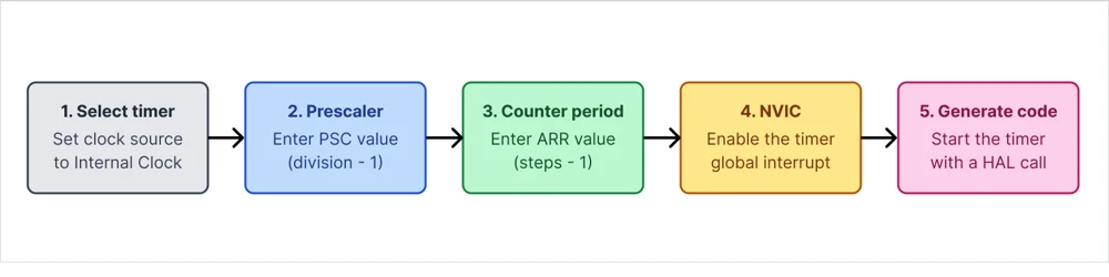
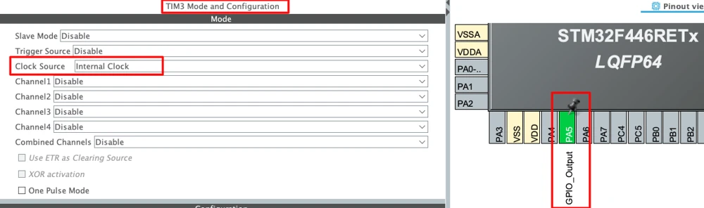
The configuration of a timer in CubeMX follows the same short sequence for almost every mode, and the diagram below shows the order of the steps. The details of CubeMX itself are explained in the STM32CubeMX article. The example in this section configures TIM3 as a time base that toggles the LED LD2 on PA5 once per second.
Timer Instance and Clock Source
Create a project for the NUCLEO-F446RE board, set the clock in the Clock Configuration tab as per your requirement, and configure PA5 as GPIO_Output for the LED. Open the Timers category and select TIM3. Set the field Clock Source to Internal Clock, which connects the counter to the timer clock that was described in the previous section. The other clock sources, such as the external clock mode, are used when the timer has to count pulses from a pin.
Prescaler and Counter Period
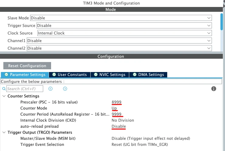
The Parameter Settings tab of TIM3 contains the values that define the period. The prescaler and the counter period fields accept the register values directly, so the value of one less than the division factor has to be entered by hand. The table below lists the settings for a period of one second with a timer clock of 90 MHz.
| Parameter | Value | Meaning |
|---|---|---|
| Prescaler (PSC) | 8999 | Divides the 90 MHz clock by 9000 to give 10 kHz |
| Counter Mode | Up | The counter counts from 0 to ARR |
| Counter Period (AutoReload Register) | 9999 | 10,000 counts at 10 kHz give 1 second |
| Internal Clock Division | No Division | The clock for filters is not divided |
| auto-reload preload | Disable | Not needed because ARR does not change at runtime |
Timer Interrupt in the NVIC
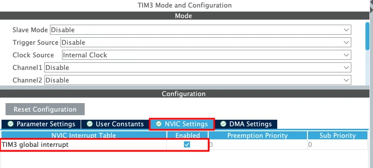
The period settings are not enough to run code on every update event. Open the NVIC Settings tab of TIM3 and tick the box TIM3 global interrupt. When the code is generated, CubeMX adds the calls HAL_NVIC_SetPriority() and HAL_NVIC_EnableIRQ() to MX_TIM3_Init(), and it creates the handler TIM3_IRQHandler() in stm32f4xx_it.c. The principles of the NVIC were explained in the GPIO interrupts article.
Generate Code and Main HAL Calls
After the code is generated, the main.c file contains the function MX_TIM3_Init(), which writes the prescaler, the counter mode, and the period into the timer registers through HAL_TIM_Base_Init().
|
1 2 3 4 5 6 7 8 9 10 |
htim3.Instance = TIM3; htim3.Init.Prescaler = 8999; htim3.Init.CounterMode = TIM_COUNTERMODE_UP; htim3.Init.Period = 9999; htim3.Init.ClockDivision = TIM_CLOCKDIVISION_DIV1; htim3.Init.AutoReloadPreload = TIM_AUTORELOAD_PRELOAD_DISABLE; if (HAL_TIM_Base_Init(&htim3) != HAL_OK) { Error_Handler(); } |
This function does not start the counter. The application starts it with HAL_TIM_Base_Start_IT(), which enables the update interrupt and then starts counting. The generated handler TIM3_IRQHandler() calls HAL_TIM_IRQHandler(&htim3), and this function clears the update flag and calls the weak callback HAL_TIM_PeriodElapsedCallback(). The application replaces this callback to receive the event.
The following code goes into main.c, with the start call in the section USER CODE BEGIN 2 and the callback in the section USER CODE BEGIN 4.
|
1 2 3 4 5 6 7 8 9 10 11 12 13 |
/* USER CODE BEGIN 0 */ void HAL_TIM_PeriodElapsedCallback(TIM_HandleTypeDef *htim) { if (htim->Instance == TIM3) { HAL_GPIO_TogglePin(GPIOA, GPIO_PIN_5); // Runs once per second } } /* USER CODE END 0 */ /* USER CODE BEGIN 2 */ HAL_TIM_Base_Start_IT(&htim3); // Enables the update interrupt and starts the counter /* USER CODE END 2 */ |
The check of htim->Instance makes sure that the action runs only for TIM3. This matters because the same callback is shared by all timers that use the HAL update interrupt, and a project may also use another timer as the HAL time base. When the program runs, the LED LD2 changes its state once per second, which gives a full blink period of two seconds. The main loop stays empty, and the CPU is free for other work.
The other HAL functions follow the same naming pattern for each mode. For example, HAL_TIM_PWM_Start() starts a PWM channel, HAL_TIM_IC_Start_IT() starts an input capture channel with an interrupt, and HAL_TIM_Encoder_Start() starts the encoder interface. Each of these functions is introduced in its own article.
Conclusion
An STM32 timer is a hardware counter that runs independently of the CPU. Its clock passes through the prescaler, the counter counts the divided pulses up to the value of the auto-reload register, and the return of the counter to zero creates an update event. The update frequency follows from the timer clock and the two register values, and this one relationship is the basis of almost every timer function. The same structure can raise periodic interrupts, generate PWM signals, capture the timing of external pulses, count encoder steps, and trigger other peripherals such as the ADC.
The three timer groups differ only in the number of features around the counter, so the knowledge from this article applies to all of them. Before using a timer in a project, it is useful to check which timer instances the device offers, which bus each one is connected to, and what the resulting timer clock is. The details differ between STM32 families, and the reference manual of the exact device remains the final source for the registers and the clock rules. With this overview complete, the next step is the timer interrupt article, which takes the example from this guide and looks at the update interrupt in more detail.
Download the Project Here
Download the CubeMX project files and HAL source code — all tested on real hardware.
If you find this useful, you can support us with a Donation as well.