STM32 GPIO Complete Guide
We just finished setting up our first STM32 project in CubeMX, and now we want to blink an LED, or maybe read a button press. Either way, we are looking at a pin on the chip and trying to work out how to turn it on.
That pin is called a GPIO pin, and GPIO is where almost every STM32 project starts. Before we touch UART, timers, or anything else, we start with GPIO.
GPIO is not complicated once we understand it properly. It only has a few moving parts, and each one has a clear job. In this guide, we will go through each of those parts, so that by the end we understand what GPIO actually is, how a pin works underneath, the different modes it can run in, and how to turn that understanding into real CubeMX and HAL code.
This is the pillar article for the GPIO section on this site, so a few topics here, like pull resistors, GPIO speed, and registers, get their own dedicated articles. We will not go too deep into them here. Let us start with the basics.
Table of contents
What is GPIO?
GPIO stands for General Purpose Input/Output. In simple terms, it is a pin that can either read a signal or send one out.
Every microcontroller needs a way to talk to the outside world, whether that means reading a button press, turning on an LED, or sensing whether a door is open or closed. None of that happens inside the chip itself. It happens through physical pins on the outside of the chip, and GPIO pins are the simplest, most flexible way to make that connection. GPIO is the doorway between our STM32 and everything connected to it.
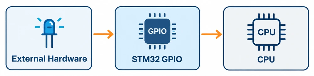
A GPIO pin can do one of two basic things. It can read a signal coming in from outside, which we call input, or it can send a signal going out, which we call output.
The signal itself is digital, so it only has two states:
- HIGH: Usually the chip’s supply voltage such as 3.3V
- LOW: 0V
A button press might pull a pin Low, and turning on an LED might mean setting a pin High. That is the whole idea at its simplest. Real GPIO pins do more than just High and Low, since they can also be handed over to other peripherals such as UART or SPI, and we will get to that a little later.
STM32 GPIO Ports and Pins
STM32 does not give us a single pile of individual pins. Instead, it groups them into ports, and each port is labelled with a letter, such as GPIOA, GPIOB, GPIOC, and so on, depending on the chip.
Inside each port, the individual pins are numbered 0 through 15, so a full pin name looks like PA0, PA5, or PB7, where the letter tells us the port and the number tells us the pin inside that port. The diagram below shows this for GPIOA.
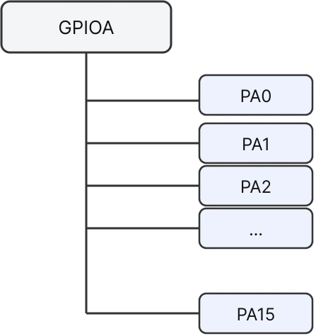
Pins are grouped into ports mainly because of how the hardware is wired internally. Pins in the same port share some circuitry and are controlled through the same set of registers. It is also easier to reason about, since setting PA5 high is a lot clearer than describing a pin by some raw number.
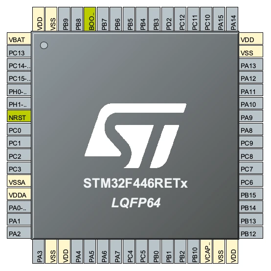
Not every STM32 chip has the same ports or the same number of pins. A small STM32C0 in a compact package might only expose GPIOA and part of GPIOB, while a larger STM32F4 in a bigger package might give us GPIOA all the way through GPIOH. The datasheet and pinout diagram for our exact chip and package show what is actually available, and CubeMX also shows this visually as soon as we select our MCU, which is the easiest way to check.
How GPIO Pin Work?
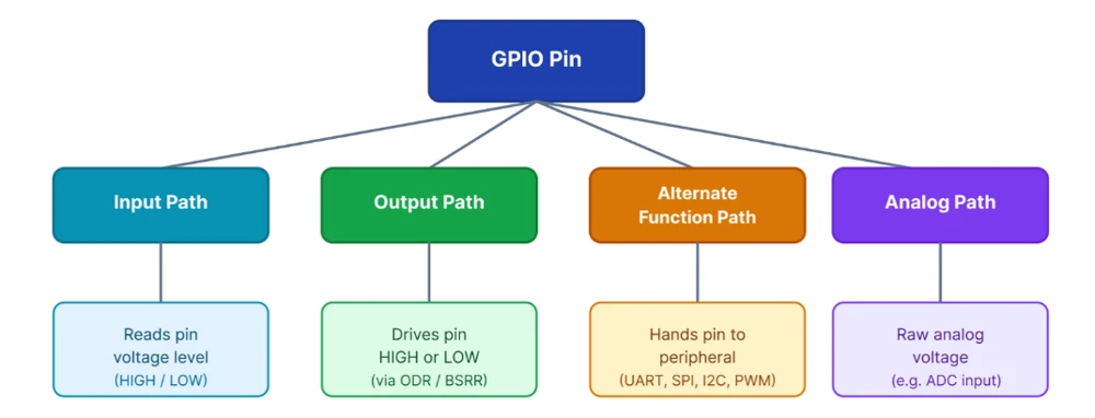
A GPIO pin is not just a wire running straight into the CPU. There is a small chain of hardware in between.
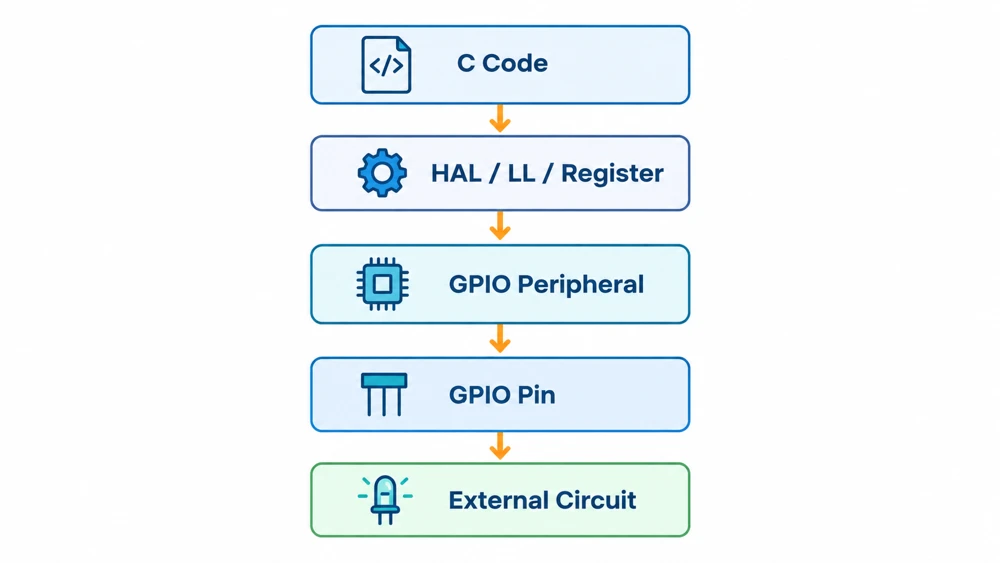
When we call a function such as HAL_GPIO_WritePin(), that call does not touch the pin directly. It writes to a register inside the GPIO peripheral, a dedicated block of hardware attached to that port, and the peripheral is the thing that actually drives the physical pin High or Low, or reads what voltage is on it.
Inside that peripheral, there are a few internal paths working together, and which one is active depends entirely on how we have configured the pin.
- An input path, used to read the pin’s voltage level
- An output path, used to drive the pin high or low
- An alternate-function path, used when another peripheral like UART or SPI takes control of the pin
- An analog path, used when the pin is connected to something like the ADC
GPIO configuration, at its core, is simply telling the peripheral which of these paths to use for a given pin.
Enabling the GPIO Clock
Before any of this works, there is one step that comes first, and that is enabling the clock for that GPIO port.
STM32 chips save power by keeping peripherals switched off until we tell them otherwise, and GPIO ports are no exception. If the clock for a port is not enabled, writes to that port’s registers simply do nothing. There is no error and no warning. The pin just ignores everything.
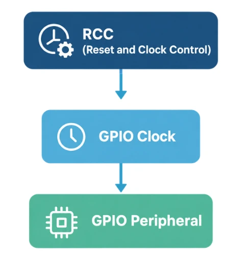
RCC stands for Reset and Clock Control, and it is the part of the chip responsible for turning peripheral clocks on and off. Every family handles this slightly differently under the hood, but CubeMX-generated code takes care of it automatically, using a line that looks something like __HAL_RCC_GPIOA_CLK_ENABLE();
We rarely need to think about this line when using CubeMX, since it is generated for us the moment we configure a pin on that port. It is still worth knowing it exists, especially when writing code by hand instead of generating it.
GPIO Modes
Every GPIO pin can run in one of four modes, and picking the right one is really the first decision we make for every pin in a project.
- Input mode is for reading something, such as a button, a switch, or a digital sensor, and the pin simply reports whether it sees High or Low.
- Output mode is for driving something, such as an LED, a relay, or a control signal to another chip, and here the MCU decides the voltage on the pin and pushes it out.
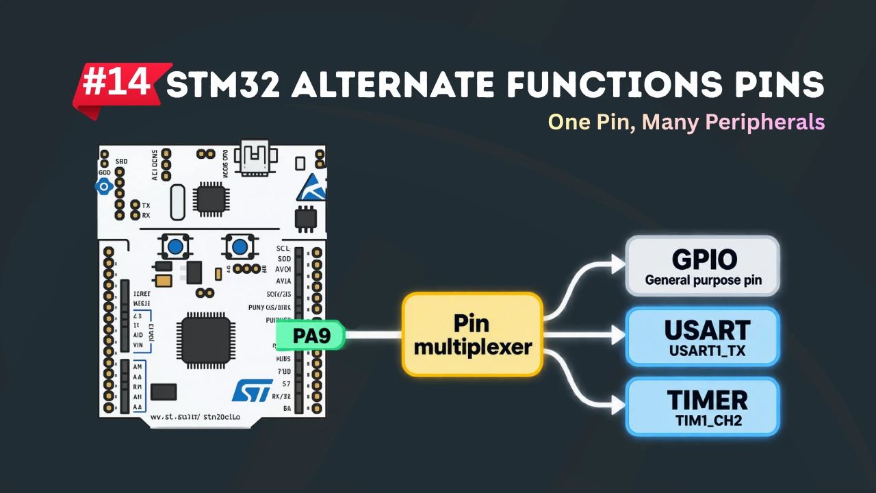
- Alternate function mode hands the pin over to a built-in peripheral, and this is how UART TX/RX, SPI, I2C, and timer PWM outputs actually work, since these are not separate physical pins but GPIO pins that have been reassigned. A pin can often serve more than one peripheral function, and CubeMX shows which ones are available for each pin on our specific chip.
- Analog mode disconnects most of the digital circuitry on the pin, and this is used for things like ADC inputs, where we want the raw analog voltage instead of a digital High/Low reading.
Getting the mode wrong, for example leaving a UART pin in plain output mode, means that peripheral simply will not work, even though everything else looks correct.
We are covering modes at a high level here on purpose. A deeper breakdown, with examples for each mode, is covered fully in a dedicated article, STM32 GPIO Modes Explained. The alternate function side specifically, where a single pin can carry UART, SPI, or PWM, is covered in STM32 Alternate Function Pins Explained.
Push-Pull vs Open-Drain
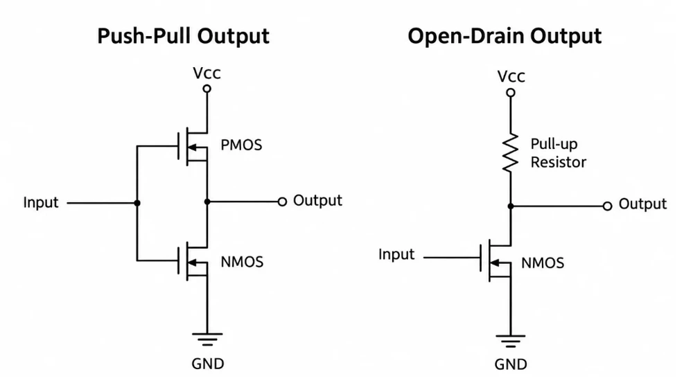
Once a pin is in output mode, there is a second question to answer: how does it actually drive that output?
- Push-pull output can actively drive both High and Low.
- Open-drain output can only pull Low, and needs an external or internal pull-up resistor to reach High.
Open-drain shows up often in shared-bus setups such as I2C, where more than one device needs to control the same line without conflicting with each other.
On the input side, a pin left with nothing connected to it is called a floating input, and it is unreliable, since it can read High or Low at random, picking up noise from nearby wires. STM32 provides built-in pull-up and pull-down resistors that can be enabled per pin, which gently hold the pin at a known level until something actively drives it otherwise.
This section is kept light on purpose, since the electrical details deserve their own space. The full comparison between push-pull and open-drain, with real circuit behavior, is covered in Push-Pull vs Open-Drain. A closer look at pull-up and pull-down resistors, including how to configure them and when a floating input actually causes problems, is covered in STM32 Pull-Up and Pull-Down Resistors.
GPIO Speed and Output Data
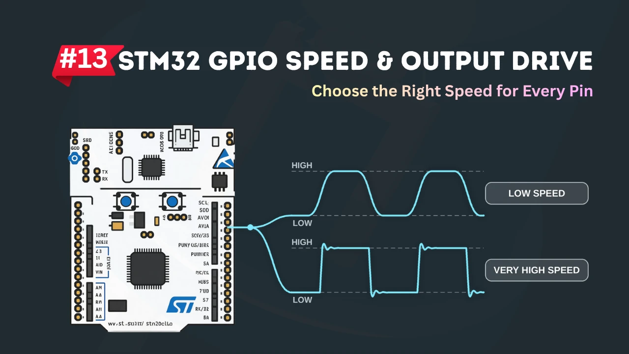
STM32 also lets us set an output speed for each pin, separate from output mode. This controls how fast the pin transitions between High and Low, or how sharp the rising and falling edges are.
A faster speed setting is not automatically better. Higher speed settings mean faster edges, and this brings more electrical noise and more overshoot on the signal. For something slow, such as an LED, a low speed setting is perfectly fine and is actually the better choice. Higher speeds matter more for fast digital signals, such as a high-frequency SPI clock line.
This is also a good place to mention the two main ways we control the pin’s output value directly:
|
1 2 |
GPIOA->ODR // Output Data Register — holds the current output state GPIOA->BSRR // Bit Set/Reset Register — sets or clears pins atomically |
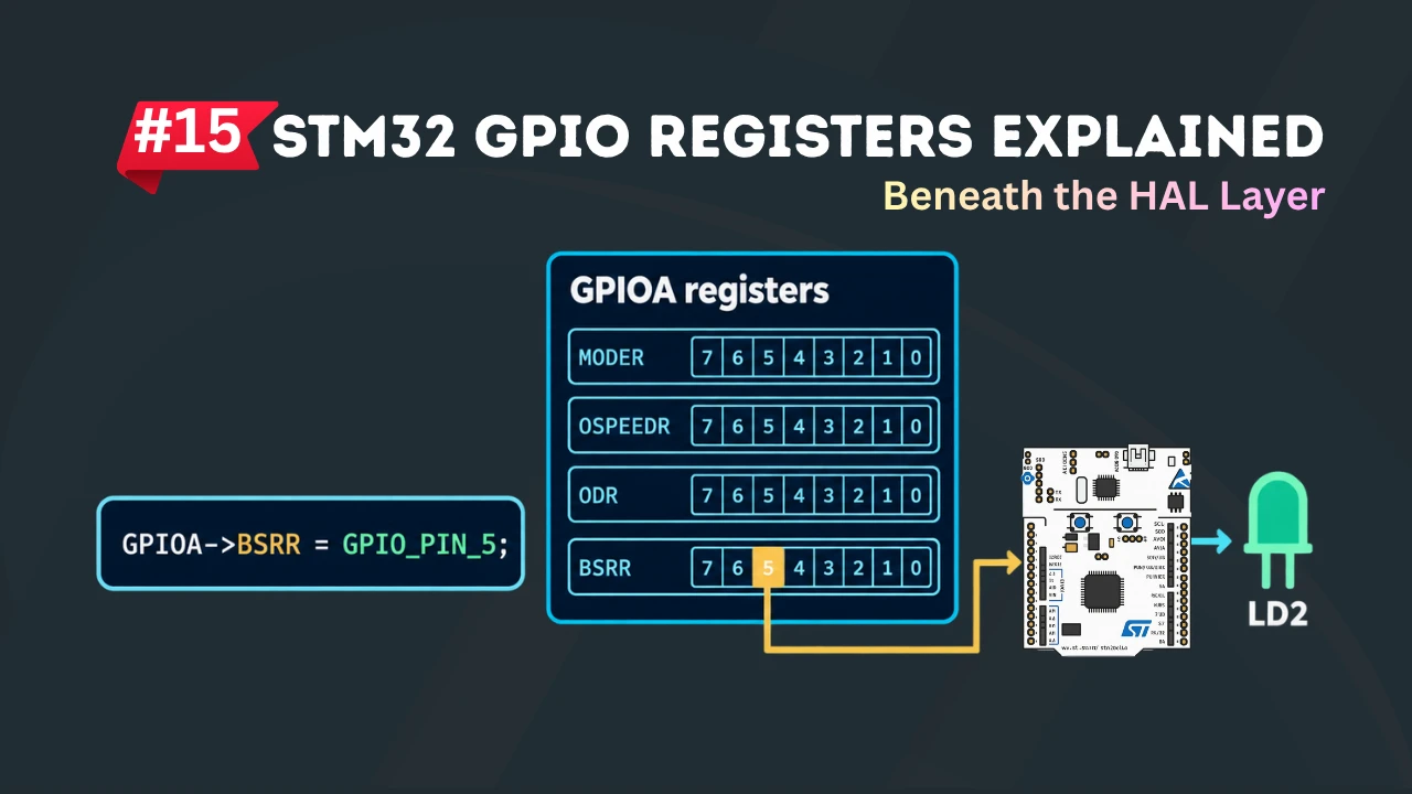
ODR is the straightforward option. We can read it or write it to see or set the pin state. BSRR is the safer option for setting individual bits, because it performs the set or clear in one atomic step instead of a read-modify-write. This detail matters more once interrupts are involved, and it is covered properly in the registers article.
The full picture on speed settings, and when they actually matter, is covered in STM32 GPIO Speed and Output Drive.
Configuring GPIO With CubeMX and HAL
In practice, we rarely type out GPIO configuration by hand, since CubeMX handles it for us.
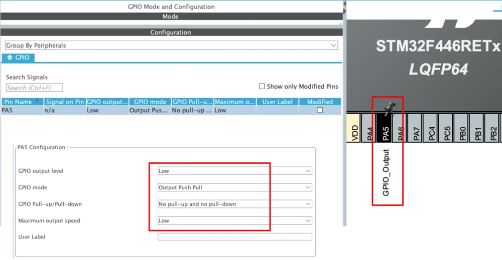
The usual workflow is to click a pin on the chip diagram in CubeMX, choose what it should do, such as GPIO_Output, GPIO_Input, or USART1_TX, set a few extra options like pull resistor and speed, and generate code. CubeMX writes out the clock enable, the GPIO_InitTypeDef structure, and the call to HAL_GPIO_Init() for us.
Once that setup is done, our day to day work with a pin comes down to three HAL functions:
|
1 2 3 |
HAL_GPIO_WritePin(GPIOA, GPIO_PIN_5, GPIO_PIN_SET); // drive HIGH or LOW HAL_GPIO_ReadPin(GPIOA, GPIO_PIN_0); // read the current state HAL_GPIO_TogglePin(GPIOA, GPIO_PIN_5); // flip HIGH/LOW |
That is genuinely most of what GPIO is used for day to day. We set a pin, read a pin, or toggle a pin, and everything else in this article is really about understanding what happens underneath those three calls.
GPIO Registers at a Glance
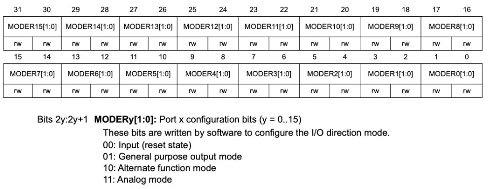
Everything covered so far, such as mode, pull resistor, speed, and output value, is ultimately stored in a small set of registers, one set per port. The table below summarizes the main ones.
| Register | What It Controls |
|---|---|
| MODER | Pin mode: input, output, alternate function, or analog |
| OTYPER | Output type: push-pull or open-drain |
| OSPEEDR | Output speed |
| PUPDR | Pull-up / pull-down configuration |
| IDR | Current input state of each pin |
| ODR | Current output state of each pin |
| BSRR | Atomic set/reset of individual pins |
| AFR | Which alternate function is assigned to a pin |
This section will not break down each bit, since that deserves its own article. A closer look at how these registers map to the HAL calls we already know, and how to write GPIO code by hand using just these registers, is covered in STM32 GPIO Registers Explained.
LED and Button Example
With the theory covered, let us put it into practice by building a small example that brings everything together: an LED we control, and a button we read.
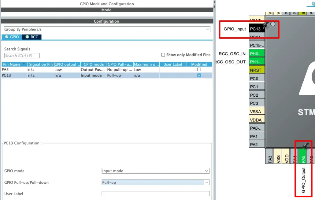
The idea is simple. We configure one pin as output and connect it to an LED, then we configure another pin as input and connect it to a push button. From there, we read the button and light the LED based on what we read.
In CubeMX, we select a pin for the LED and set it to GPIO_Output, then select another pin for the button and set it to GPIO_Input, enabling the internal pull-up or pull-down depending on how the button is wired, and generate the code.
The generated MX_GPIO_Init() function handles the clock enable and register setup for both pins, so our job is only to use them.
|
1 2 3 4 5 6 7 8 9 10 11 |
while (1) { if (HAL_GPIO_ReadPin(GPIOC, GPIO_PIN_13) == GPIO_PIN_RESET) //If the button is pressed { HAL_GPIO_WritePin(GPIOA, GPIO_PIN_5, GPIO_PIN_SET); // Turn the LED ON } else { HAL_GPIO_WritePin(GPIOA, GPIO_PIN_5, GPIO_PIN_RESET); // Turn the LED OFF } } |
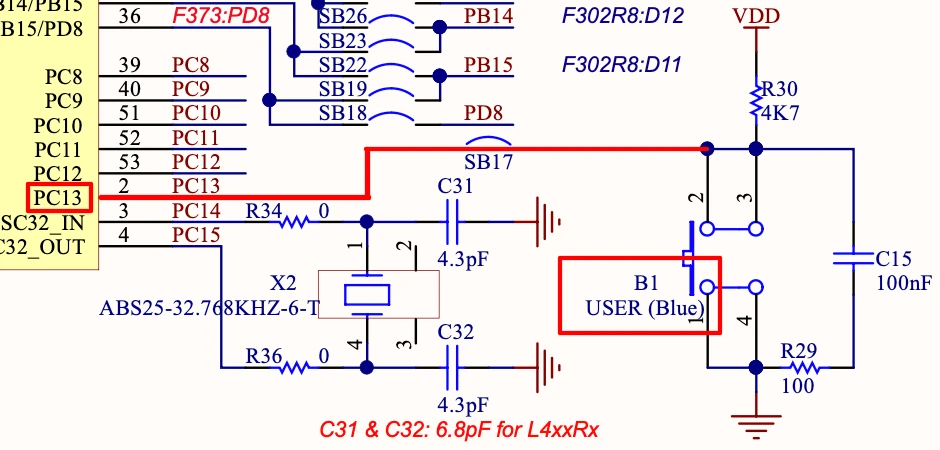
One detail that catches a lot of people off guard here is active-low versus active-high behavior. On many Nucleo boards, the onboard button pulls the pin Low when pressed, not High, which is why the check above looks for GPIO_PIN_RESET instead of GPIO_PIN_SET. It is always worth checking the specific board’s schematic before assuming which state means “pressed.”
The Video below shows the output of the code. The LED turns ON when the button is pressed and it turns OFF when the button is released.
Wrapping Up
GPIO looks simple from the outside, but there is a real chain of hardware underneath it. A peripheral clock has to be enabled first. Then a mode decides what the pin is actually for. From there, an output type and pull configuration shape its electrical behavior, and underneath all of it, everything comes down to a set of registers.
None of these pieces are complicated on their own. We enable the clock, pick a mode, configure the electrical details, and use HAL_GPIO_WritePin(), HAL_GPIO_ReadPin(), or HAL_GPIO_TogglePin() to actually use the pin. CubeMX generates almost all of this for us, which is exactly why GPIO feels straightforward once we have done it a few times.
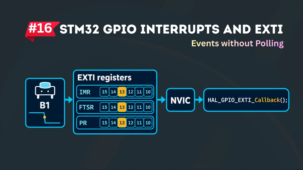
This article was meant to give us that full picture without getting lost in any single piece of it. The deeper dives, covering modes, push-pull versus open-drain, pull resistors, speed, alternate functions, registers, and interrupts, are each covered properly in their own articles, linked throughout this guide. Building the LED and button example is a good next step, since everything after that will make a lot more sense once we have seen it work on real hardware.
Download the Project Here
Download the CubeMX project files and HAL source code — all tested on real hardware.
If you find this useful, you can support us with a Donation as well.