STM32 GPIO Interrupts and EXTI
In the earlier STM32 GPIO articles, the CPU read a pin whenever the program asked for it. The program decides when to look at the pin, and it has to keep looking for as long as it wants to notice a change. This approach is simple, and it is enough for many small programs. However, It becomes inefficient when the signal is rare or when the reaction must be fast. For example with a button press, a pulse from a sensor, or a signal from another chip that says its data is ready.
A GPIO interrupt reverses this arrangement. A hardware block watches the pin, and the CPU is informed only when the pin changes in the way we selected. On STM32 devices, this block is the EXTI controller. It works together with the NVIC to pause the normal program and run a handler function. This is the final article of the GPIO section, and it introduces the ideas that the later interrupt articles will be build on.
In this article, we will begin with the idea of an external interrupt and a comparison between polling and interrupts. Then we will look at the EXTI controller, the mapping between GPIO pins and EXTI lines, the edge settings, and the role of the NVIC. After that, we will follow the complete interrupt flow, from configuring EXTI in CubeMX to writing a button interrupt with the HAL callback. In the later sections, we will cover switch bounce, and a working example on the NUCLEO-F446RE board that uses a button to control an LED, a counter, and a state variable.
The examples in this article use the STM32F4 series and the HAL library. Some details of EXTI differ between STM32 families, and these differences are marked where they matter. This article is part of the STM32 GPIO tutorial series.
Table of contents
What Is an External Interrupt
An interrupt is a request that makes the CPU pause the code it is running, execute a short function called the interrupt handler, and then continue from the point where it stopped. An external interrupt is an interrupt whose source is a signal outside the microcontroller. In most designs, this signal is the voltage level of a GPIO pin, for example the output of a push button or a sensor that pulls a line low when new data is ready.
The interrupt handler is an ordinary C function, but the program never calls it. The hardware calls it when the selected change happens on the pin. This makes interrupts a good fit for events that arrive at unpredictable moments. A button can be pressed while the CPU is busy with a calculation or a data transfer, and the handler still starts after a very small number of clock cycles. The main program does not need any code for monitoring the pin, and it does not need to know when the event will happen.
Polling vs Interrupts
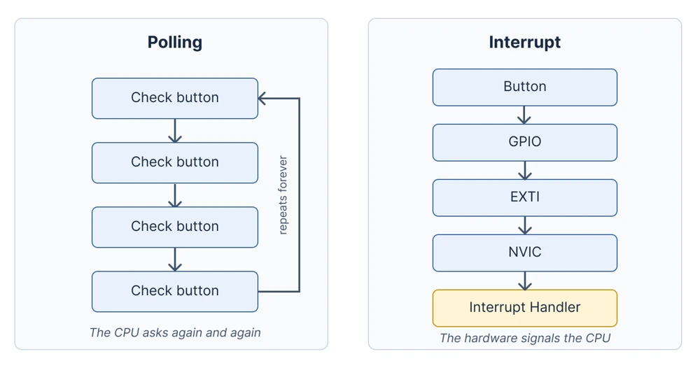
Polling and interrupts are two ways of noticing a change on a pin. In polling, the CPU reads the pin in a loop and compares the result with the previous value. In the interrupt approach, a hardware block watches the pin and informs the CPU only when something has changed. The diagram below shows how the two approaches differ.
| Polling | Interrupt |
|---|---|
| The CPU repeatedly checks the pin | The hardware signals the CPU |
| Simple to write and to follow | More event-driven |
| Can waste CPU time on unchanged inputs | The CPU can perform other work in the meantime |
| Easy for simple tasks | Useful for asynchronous events |
The two approaches differ in who is responsible for watching the pin. In polling, the program does the watching, so the delay before the reaction depends on how often the loop reaches the check. A long delay or a slow function in the same loop can make the program notice a button press late, or miss it completely if the press is shorter than one loop cycle. With an interrupt, a hardware block watches the pin independently of the CPU, so the reaction time does not depend on what the main program is doing at that moment.
Polling is still a correct choice for simple tasks. For example, a program that reads a switch once every few hundred milliseconds to select a mode does not gain much from an interrupt. Also, polling keeps the program flow easy to follow because everything happens in one place. Interrupts, on the other hand, add some complexity because the handler can run at any point of the main program. The extra effort is worth it when the event is rare, short, or time-critical, or when the CPU has other work to do in the meantime.
What Is EXTI in STM32
EXTI stands for External Interrupt/Event Controller. It is a peripheral that sits between the input signals and the interrupt controller of the CPU. It monitors a set of signals called EXTI lines, detects the edge that we have selected on each line, and records the detection in a pending flag. If the line is enabled, the pending flag becomes an interrupt request that is passed on to the NVIC.
Not all EXTI lines are connected to GPIO pins. On the STM32F4 series, the lines 0 to 15 are connected to the GPIO pins, and the remaining lines are connected to internal sources such as the programmable voltage detector, the RTC alarm, the RTC wakeup timer, and the USB wakeup signals. This article uses only the GPIO lines.
The word event in the name has a separate meaning. EXTI can generate an interrupt or an event for each line. An interrupt makes the CPU run a handler function, while an event is a pulse that does not run any code. An event can wake the CPU from a sleep mode or trigger another peripheral. It is generally useful in low-power designs. In this article, we focus on only interrupts.
EXTI Registers
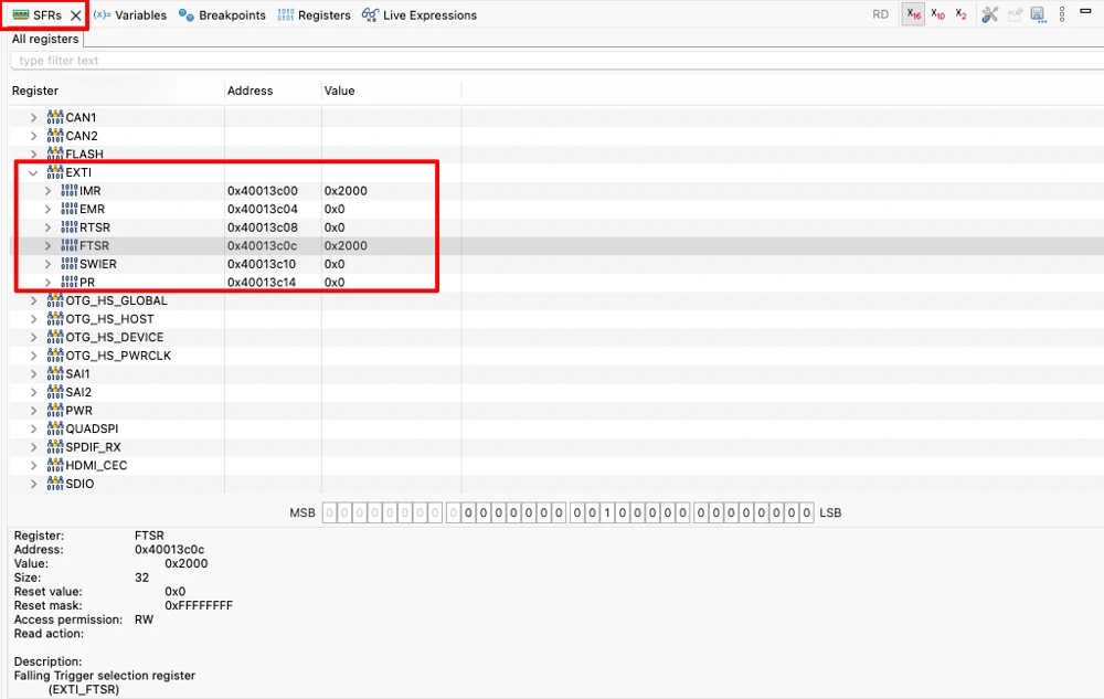
Like every other peripheral, EXTI is also controlled by registers, and each of them has one bit per line. On the STM32F4 series, the interrupt mask register IMR enables or disables the interrupt of a line, and the event mask register EMR does the same for events. The rising trigger selection register (RTSR) and the falling trigger selection register (FTSR) choose the edges that EXTI detects. The software interrupt register (SWIER) can raise an interrupt from code, and the pending register (PR) shows which lines have detected an edge.
The pending register needs special attention. When EXTI detects the selected edge, it sets the bit of that line in PR, and the bit stays set until the software clears it by writing a 1 to it. If the bit is not cleared, the NVIC keeps requesting the interrupt, and the handler runs again and again. The HAL function HAL_GPIO_EXTI_IRQHandler() clears the bit for us, which is one reason to keep the generated handler code in place. The function HAL_GPIO_Init() writes the other registers when we select an interrupt mode for a pin.
GPIO to EXTI Mapping
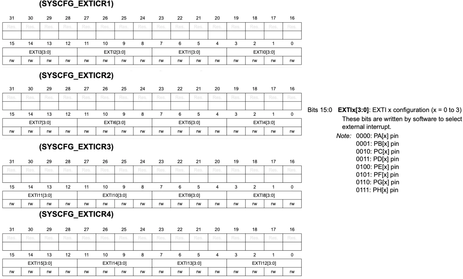
Each EXTI line n can be connected to the pin n of one GPIO port at a time. The line EXTI0 can listen to PA0, PB0, or PC0, and the line EXTI13 can listen to PA13, PB13, or PC13. The selection is made by a multiplexer in front of each line, and the multiplexer is controlled by the SYSCFG_EXTICR registers, which use four bits per line. HAL enables the SYSCFG clock and writes the correct field inside HAL_GPIO_Init(), so we normally do not have to do it by hand. The diagram below shows the structure for the lines 0 and 13.
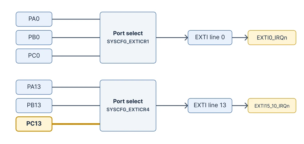
The practical result is that two pins with the same pin number but different ports cannot both be used as interrupt sources at the same time. PA5 and PC5 both need the line EXTI5, so only one of them can be connected to it. It is useful to keep this in mind during pin planning, and to spread the interrupt pins over different pin numbers.
The structure described here belongs to the STM32F4 series. Newer families such as the STM32G0 and the STM32U5 have a redesigned EXTI peripheral, where the port selection is part of EXTI itself and the rising and falling edges have separate pending registers. The idea of connecting one port pin to one line stays the same, but the register names and the HAL callbacks can differ, so the reference manual of the exact device remains the final source for the mapping rules.
Shared Interrupt Vectors
The EXTI lines do not each have their own entry in the NVIC. The lines 0 to 4 have one interrupt each, but the lines 5 to 9 share one interrupt, and the lines 10 to 15 share another one. The table below lists the interrupts of the STM32F4 series.
| EXTI lines | NVIC interrupt | Handler name in the startup file |
|---|---|---|
| 0 to 4 (one each) | EXTI0_IRQn to EXTI4_IRQn | EXTI0_IRQHandler to EXTI4_IRQHandler |
| 5 to 9 | EXTI9_5_IRQn | EXTI9_5_IRQHandler |
| 10 to 15 | EXTI15_10_IRQn | EXTI15_10_IRQHandler |
The user button of the NUCLEO-F446RE board is connected to PC13, so it uses the line 13 and the handler EXTI15_10_IRQHandler. When several pins share one handler, the code has to find out which pin caused the interrupt. The HAL driver handles this by passing the pin mask as the argument of the callback function, and we will use this argument in the examples below.
Rising and Falling Edge Triggers
EXTI does not look at the level of a pin. It looks at the transitions between the levels, which are called edges. An edge is the moment at which the voltage moves from one logic level to the other, and EXTI can be told to react to the rising edge, the falling edge, or both. The diagram below shows the three options.
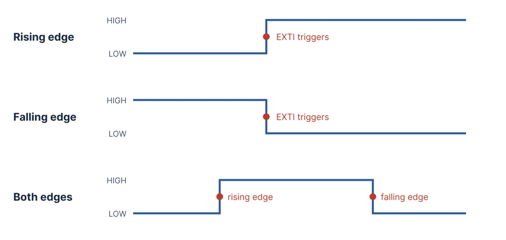
The correct choice depends on the wiring of the input. A button that connects the pin to ground, with a pull-up resistor holding the pin high, gives a falling edge when it is pressed and a rising edge when it is released. A button that connects the pin to the supply voltage, with a pull-down resistor, gives the opposite. The user button B1 of the NUCLEO-F446RE board is of the first kind, so a falling edge marks the press. The pull-up and pull-down article explains this wiring in more detail.
The both-edges option is used when the program needs to know when a signal starts and when it ends. For example, to measure the length of a pulse or to track the press and the release of a button. On the STM32F4 series, the callback only receives the pin number, so the code has to read the pin with HAL_GPIO_ReadPin() to find out which edge has occurred. One more advantage of edge detection is that EXTI latches the edge in the pending register. A short pulse is therefore recorded even if the CPU is busy at that moment, while a polling loop could miss the same pulse.
What Is the NVIC in STM32
The NVIC is the Nested Vectored Interrupt Controller, and it is part of the Cortex-M core. EXTI creates the interrupt request, and the NVIC decides whether and when the CPU acts on it. Each interrupt source of the device has its own entry in the NVIC, where it can be enabled, disabled, and given a priority.
The name describes its two main features. The word vectored means that the CPU receives the address of the handler directly from the vector table, so no software is needed to search for the source of the interrupt. The word nested means that an interrupt with a higher priority can interrupt a handler with a lower priority that is already running. On the STM32F4 series, a lower priority number means a higher priority, and the device implements four priority bits, which gives sixteen levels.
An interrupt from a GPIO pin has to pass two enable switches. The first one is the mask bit of the line in EXTI, and the second one is the enable bit of the interrupt in the NVIC. If either of them is off, the handler never runs. CubeMX sets both when we select an external interrupt mode for a pin and tick the interrupt in the NVIC settings, and it generates the calls HAL_NVIC_SetPriority() and HAL_NVIC_EnableIRQ() in the initialization code.
EXTI Interrupt Flow
The complete path from the pin to the application code has several stages, and each of them is handled by a different block. The diagram below follows one button press from the electrical change on the pin to the action in the application.
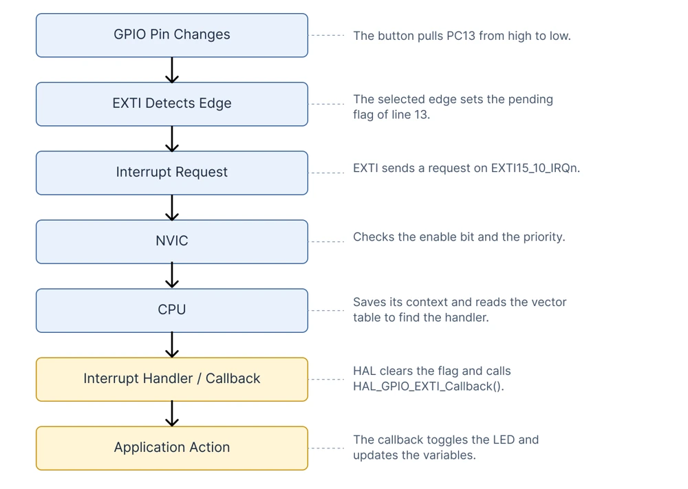
The flow starts when the voltage of the pin crosses from one level to the other. EXTI compares the change with the edge that was selected in RTSR and FTSR registers, and when they match, it sets the pending bit of the line. If the line is unmasked in IMR, EXTI passes a request to the NVIC. The NVIC checks that the interrupt is enabled, compares its priority with the priority of any code that is currently running, and signals the CPU if the new interrupt is allowed to proceed.
The CPU then saves a part of its registers on the stack, reads the address of the handler from the vector table, and starts the handler. In a HAL project, this handler is EXTI15_10_IRQHandler() in the stm32f4xx_it.c file. It calls HAL_GPIO_EXTI_IRQHandler(), which clears the pending bit and calls the function HAL_GPIO_EXTI_Callback(). This callback is the place where the application code is written. When the callback returns, the CPU restores its registers and continues the main program from the point where it was interrupted.
Configuring EXTI in CubeMX
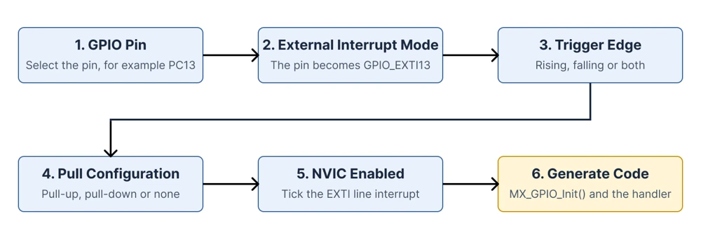
The configuration of an external interrupt in CubeMX has a short sequence of settings, and the diagram below shows their order. Details of CubeMX itself are explained in the STM32CubeMX article.
Pin Mode and Trigger Edge
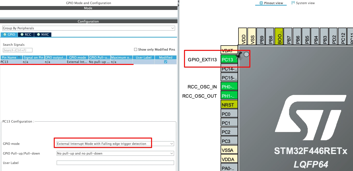
In the Pinout view, click the pin and select the entry GPIO_EXTIn from the list, where n is the pin number. Then open the GPIO category under System Core and select the pin. The field GPIO mode offers three interrupt modes: External Interrupt Mode with Rising edge trigger detection, with Falling edge trigger detection, and with Rising/Falling edge trigger detection.
Pull Configuration
The field GPIO Pull-up/Pull-down sets the internal resistor of the pin, and the correct value follows from the wiring of the button. The B1 button of the NUCLEO-F446RE board already has a pull-up resistor on the board, so the setting is No pull-up and no pull-down.
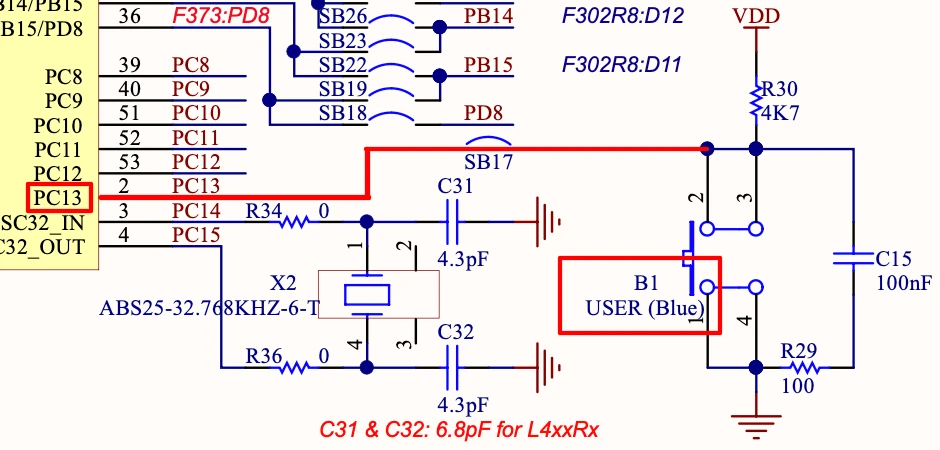
For a button that is connected on an external board and wired to ground, the internal pull-up is the usual choice. An interrupt input with no pull resistor and no external driver floats, and the noise on the pin can then create many false interrupts.
NVIC Settings
Selecting the interrupt mode of the pin is not enough. Open the NVIC category under System Core and tick the box EXTI line[15:10] interrupts for PC13. The priority can stay at the default value for now. When the code is generated, CubeMX adds the calls HAL_NVIC_SetPriority() and HAL_NVIC_EnableIRQ() at the end of MX_GPIO_Init(), and it creates the handler function EXTI15_10_IRQHandler() in stm32f4xx_it.c.
![STM32CubeMX NVIC settings with the EXTI line[15:10] interrupts option ticked for the PC13 button](https://stm32guide.com/wp-content/uploads/2026/10/STM32-EXTI-Nvic-Setting.webp)
HAL EXTI Callback
The basic example uses the button B1 to toggle the LED LD2. The diagram below shows the parts that take part in it.
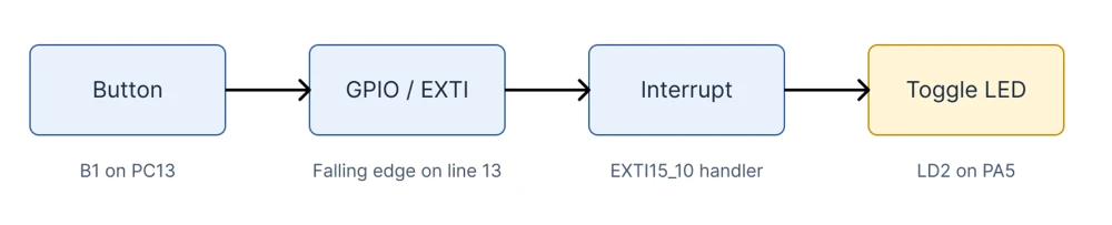
The generated handler in stm32f4xx_it.c contains one call that connects the interrupt to HAL.
|
1 2 3 4 5 6 7 8 9 10 |
void EXTI15_10_IRQHandler(void) { /* USER CODE BEGIN EXTI15_10_IRQn 0 */ /* USER CODE END EXTI15_10_IRQn 0 */ HAL_GPIO_EXTI_IRQHandler(GPIO_PIN_13); /* USER CODE BEGIN EXTI15_10_IRQn 1 */ /* USER CODE END EXTI15_10_IRQn 1 */ } |
The function HAL_GPIO_EXTI_IRQHandler() checks the pending bit of the pin, clears it, and calls HAL_GPIO_EXTI_Callback() with the pin mask as the argument. In the HAL driver, this callback is declared as a weak function with an empty body. A weak function can be replaced by defining a function with the same name in another file, which is how the application receives the event. The following version goes into the section USER CODE BEGIN 0 of main.c.
|
1 2 3 4 5 6 7 |
void HAL_GPIO_EXTI_Callback(uint16_t GPIO_Pin) { if (GPIO_Pin == GPIO_PIN_13) { HAL_GPIO_TogglePin(GPIOA, GPIO_PIN_5); } } |
The check of GPIO_Pin makes sure that the action runs only for the button. This matters when more than one interrupt pin is being used in the project. This version works fine, but it will sometimes toggle the LED twice for one press, and the next section explains the reason.
Button Debouncing with EXTI
Switch Bounce
A mechanical switch does not change from open to closed in a single clean step. When the contacts meet, they bounce off each other for a short time, and the electrical connection opens and closes several times before it settles. The duration of this bouncing is usually a few milliseconds, although it varies from well below one millisecond to tens of milliseconds depending on the switch. A polling loop that samples the pin every few milliseconds usually does not see it, but EXTI reacts to every single edge. One physical press can therefore create several interrupts.
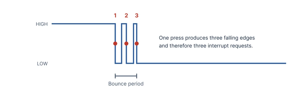
Hardware Debouncing
Bounce can be removed before the signal reaches the microcontroller. The common solution is a resistor and a capacitor that form a low-pass filter on the button line, which smooths the fast transitions into one slow transition. The input of an STM32 GPIO pin has a Schmitt trigger, so the slow edge is converted into a clean digital edge. A resistor of 10 kΩ and a capacitor of 100 nF have a time constant of 1 ms, and the values can be changed to match the switch. Dedicated debounce chips are also available for designs where the button signal has to be very clean.
Hardware debouncing needs no code and uses no CPU time, which makes it the most reliable option. The cost is additional components and board space, and the filter time is fixed once the board is built. Many development boards include a small filter on the button, but it should not be assumed that it removes all of the bounce, and the schematic of the board shows what is actually fitted.
Software Debouncing
When the board has no filter, the firmware has to ignore the extra edges. There are several ways to do this, and they differ in how much CPU time they use and how well they handle the cases that go wrong.
Delay-Based Approaches
The simplest idea is to wait for the bounce to end. After the interrupt, the code waits for 20 ms with HAL_Delay() and then reads the pin. This method works on a small test program, but it has serious limits. A delay inside the handler blocks the CPU, and it can block every interrupt that has the same or a lower priority. With the default HAL settings, a call of HAL_Delay() inside an interrupt handler can stop the whole program. Moving the delay to the main loop avoids this, but the CPU still spends the waiting time doing nothing, which removes the benefit of using an interrupt.
Timestamp Lockout
A better approach uses the system tick. The callback reads the time with HAL_GetTick() and compares it with the time of the last accepted event. If the difference is smaller than the lockout time, for example 50 ms, the event is treated as bounce and ignored. The callback never waits, and the CPU stays free. The working example in this article uses this method.
The lockout has one limit. It measures the time from the last accepted edge, so it covers the bounce at the start of a press, but it does not cover the bounce at the release. If the button is held for longer than the lockout time, a bounce at the release can create a new falling edge that is accepted as a second press. For many projects this is acceptable, and for the others the next method is more robust.
Timer and State Machine
The most robust design separates the detection of the edge from the decision. When the first edge arrives, the handler does not act on it. It only changes the state to debouncing, disables the interrupt of the pin, and starts a timer for the debounce time. When the timer expires, a second handler reads the pin. If the pin still has the pressed level, the press is confirmed, and if it has returned to the idle level, the edge is dismissed as noise. The same sequence is then repeated for the release. The diagram below shows the four states.
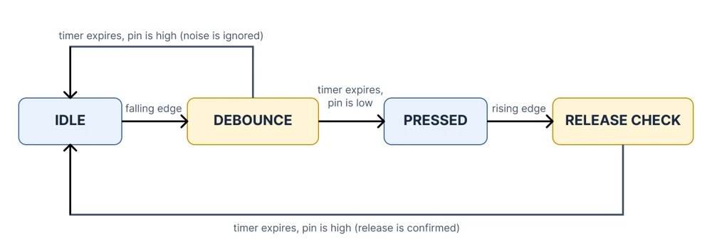
This design takes more code than the other methods, and it needs a timer that is set up for a one-shot interrupt. In return, it handles the press and the release in the same way, and it can report a clean press event to the rest of the program. The timer peripherals are covered later in the series, and until then the timestamp lockout is a sound choice for learning and for most small projects.
STM32 Button Interrupt Example
This example uses the user button B1 of the NUCLEO-F446RE board to control three things at once. Every press toggles the LED LD2 on PA5, increases a counter, and switches an application state between idle and active. Switch bounce is handled with the timestamp lockout from the previous section, with a lockout time of 50 ms.
Step 1: Create the Project
Create a new STM32CubeIDE project for the NUCLEO-F446RE board. Configure the clock as per your requirement, and read STM32 Clock System Explained if you are new to clock configuration. Configure PC13 as GPIO_EXTI13 and PA5 ad GPIO_Output for the LED.
Step 2: Configure the Button
In the Pinout & Configuration tab, open the GPIO category and select PC13. Check that the field GPIO mode shows External Interrupt Mode with Falling edge trigger detection, and that the pull setting is No pull-up and no pull-down. The board already contains the pull-up resistor of the button, so the pin is high when the button is released and low when it is pressed.
Step 3: Enable the Interrupt
Open the NVIC category under System Core and make sure that EXTI line[15:10] interrupts is ticked. Leave the priority at the default value. Then save the project and generate the code.
Step 4: Add the Variables
Open main.c and add the type, the lockout constant, and the variables in the user code sections. The variables that the callback changes are declared volatile.
|
1 2 3 4 5 6 7 8 9 10 11 12 |
/* USER CODE BEGIN 0 */ typedef enum { APP_IDLE = 0, APP_ACTIVE } AppState_t; #define DEBOUNCE_MS 50U // Edges closer than this to the last accepted press are ignored volatile uint32_t press_count = 0U; // Number of accepted button presses volatile AppState_t app_state = APP_IDLE; // Application state, changed on each press static uint32_t last_press_tick = 0U; // Time of the last accepted press in ms |
Step 5: Write the Callback
Add the callback in the user section as well. The function first compares the current time with the time of the last accepted press. If the difference is smaller than the lockout time, the edge is treated as bounce, and the function returns. Otherwise, it stores the new time, increases the counter, toggles the LED, and switches the state. The subtraction of two unsigned values stays correct even when the tick counter wraps around.
|
1 2 3 4 5 6 7 8 9 10 11 12 13 14 15 16 17 18 |
void HAL_GPIO_EXTI_Callback(uint16_t GPIO_Pin) { if (GPIO_Pin == GPIO_PIN_13) { uint32_t now = HAL_GetTick(); // Safe to call inside an interrupt, it only reads the counter if ((now - last_press_tick) < DEBOUNCE_MS) { return; // The edge is part of the bounce, so it is ignored } last_press_tick = now; press_count++; HAL_GPIO_TogglePin(GPIOA, GPIO_PIN_5); app_state = (app_state == APP_IDLE) ? APP_ACTIVE : APP_IDLE; } } /* USER CODE END 0 */ |
The main loop stays empty. The CPU is free to do other work while it waits, and the button is handled entirely by the interrupt. Notice that the callback uses only HAL_GetTick() for the timing and never calls HAL_Delay().
Step 6: Result
Build the project and flash it to the board. The LED changes its state with every press of Button, and it keeps the new state until the next press. To see the other two values, start a debug session and add press_count and app_state to the Live Expressions view of STM32CubeIDE. The counter increases by exactly one for every press, and the state alternates between APP_IDLE and APP_ACTIVE.
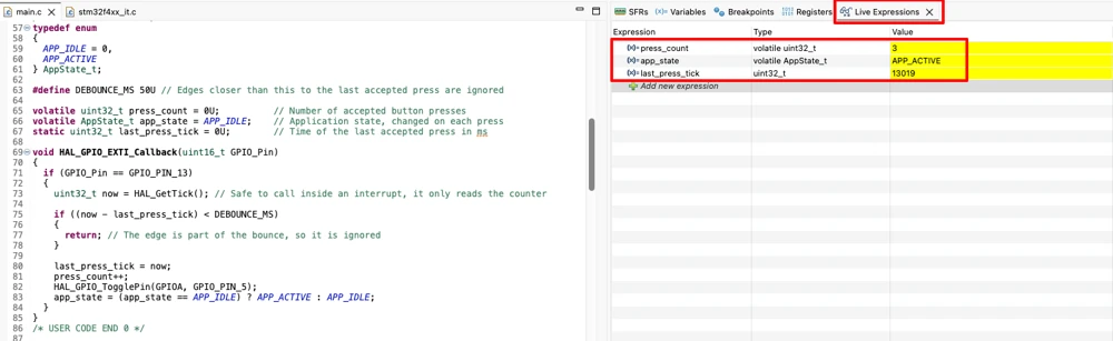
To see the effect of bounce, change DEBOUNCE_MS to 0 and run the program again. With no lockout, the counter sometimes jumps by two or more for a single press, and the LED occasionally ends in the wrong state because it was toggled an even number of times. Setting the value back to 50 removes this behavior, which confirms that the extra interrupts come from the switch and not from the code.
Conclusion
A GPIO interrupt lets a hardware block watch a pin while the CPU does other work. The EXTI controller detects the selected edge on a line and records it in the pending register, and the NVIC decides whether the CPU should respond. The CPU then runs the interrupt handler, which in a HAL project clears the pending flag and calls HAL_GPIO_EXTI_Callback() with the pin mask. The mapping of pins to lines, the choice of the edge, and the two enable switches in EXTI and in the NVIC are the main settings that decide whether the chain works.
A reliable design also depends on the signal and on the handler. Mechanical switches bounce, so one press can create several edges, and this must be handled with a hardware filter, a timestamp lockout, or a timer with a state machine. The handler itself should stay short, it should never call HAL_Delay(), and the variables it shares with the main program should be volatile. The details of EXTI differ between STM32 families, so the reference manual of the exact device is the final source for the mapping rules, the registers, and the callback names. With this article, the GPIO section is complete, and the next step is a closer look at the interrupt system itself.
Download the Project Here
Download the CubeMX project files and HAL source code — all tested on real hardware.
If you find this useful, you can support us with a Donation as well.