STM32 GPIO Modes Explained
Every GPIO pin on an STM32 microcontroller can be used for more than one purpose. A pin can read a button, drive an LED, or hand itself over to a peripheral such as UART or SPI. The mode you set on that pin decides which of these jobs it performs.
In this guide, we will go through all four GPIO modes on STM32: Input, Output, Alternate Function, and Analog. We will explain what each mode does, when to use it, and where beginners usually go wrong.
Table of contents
What Are GPIO Modes
GPIO mode answers a single question: what function is this pin performing?
Every STM32 GPIO pin can be set to one of four modes. The diagram below shows the four options.
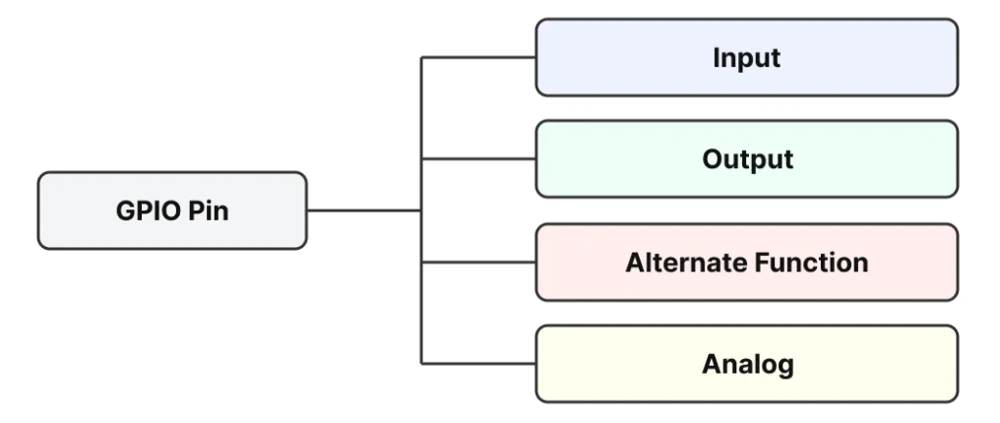
Only one mode can be active on a pin at a time. If the mode is set incorrectly, the pin will not behave as expected, even if the surrounding code and wiring are correct.
GPIO Input Mode
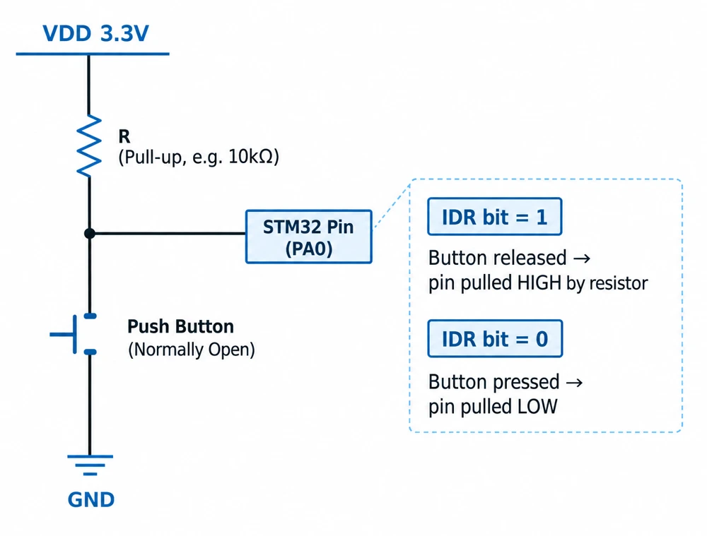
In Input mode, the microcontroller does not drive the pin. It reads the voltage that is already present on the pin, and does nothing to change it.
The key points to understand are:
- The pin reads an external digital signal. Some other circuit is applying a voltage to the pin, and STM32 simply checks its state.
- This reading is stored in the IDR (Input Data Register). Every pin has a corresponding bit in this register.
- The value is either High or Low. There is no other state in between, regardless of the actual voltage present on the pin.
When a pin is set to Input mode and nothing is connected to it, the pin does not settle at a fixed value. It floats, and can pick up electrical noise from nearby wiring. This can cause the reading to change unpredictably. STM32 provides pull configurations to prevent this:
- Floating input — no internal pull resistor is used. This is acceptable only when an external signal always drives the pin firmly.
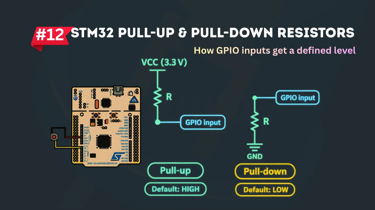
- Pull-up — an internal resistor holds the pin High when nothing else is driving it.
- Pull-down — an internal resistor holds the pin Low when nothing else is driving it.
A pull-up or pull-down resistor only affects the pin when no external signal is present. It does not interfere with a genuine input signal.
Common uses of Input mode include:
- Push button — the pin reads High or Low depending on the button state and wiring.
- Digital sensor — a sensor that outputs a clean High or Low signal, such as a limit switch.
- External interrupt source — a pin configured to trigger code execution when its state changes.
GPIO Output Mode
In Output mode, the microcontroller drives the pin. The pin’s voltage is set by the program, not by an external circuit.
The program sets the pin High or Low, and STM32 applies that voltage on the pin. There are two output configurations available:
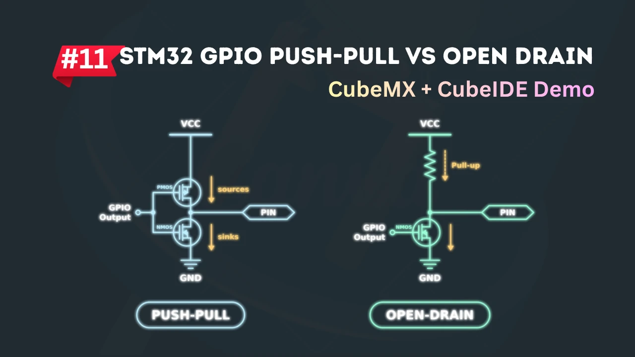
- Push-pull — the pin can actively drive both High and Low. This is the standard configuration for most output uses, such as driving an LED.
- Open-drain — the pin can only actively pull Low. To reach a High state, an external or internal pull-up resistor is required. This configuration is used on shared buses such as I²C, where multiple devices may need to control the same line.
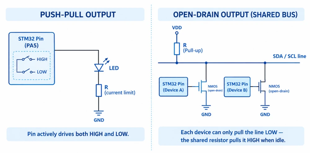
Open-drain output exists to prevent conflicts on a shared line. If two devices could actively drive High and Low at the same time on the same wire, it would create a short circuit. Open-drain avoids this by allowing devices to pull the line Low, while a shared pull-up resistor brings it High when no device is pulling it down.
Common uses of Output mode include:
- LED — turned on and off directly by the program.
- Control signal — used to enable or reset another component.
- Enable line — used to activate or deactivate part of a circuit.
GPIO Alternate Function Mode
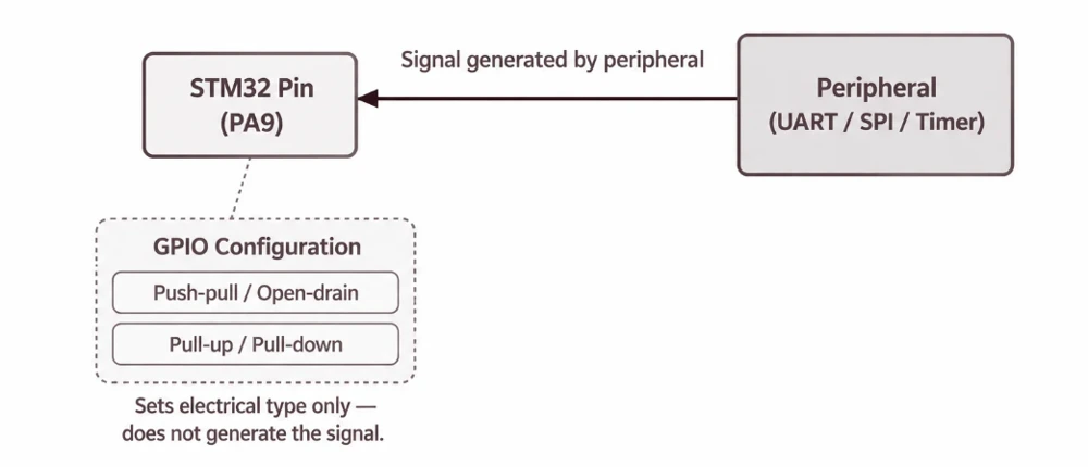
In Alternate Function mode, control of the pin is handed over to a peripheral inside the microcontroller.
For example, when a pin is used as UART TX, the program does not manually toggle the pin High and Low to transmit data. The UART peripheral generates the correct signal and timing automatically. The role of the program is only to configure the pin so that the UART peripheral can use it.
Even though the peripheral controls the signal, GPIO configuration still determines important electrical properties. Settings such as push-pull versus open-drain, and pull-up versus pull-down, still apply in Alternate Function mode. The peripheral decides what the signal carries and GPIO configuration decides how that signal behaves electrically.
Peripherals commonly used with Alternate Function pins include:
- UART — serial communication on TX and RX lines.
- SPI — clock, MISO, and MOSI lines.
- I²C — SDA and SCL lines, typically configured as open-drain with pull-up resistors.
- Timer/PWM — a timer channel drives the pin to generate a PWM waveform, commonly used for LED dimming or motor control.
Not every pin supports every peripheral function. Each pin has a defined set of alternate functions it can be mapped to. This should be confirmed in the datasheet or in CubeMX before wiring a circuit.
GPIO Analog Mode
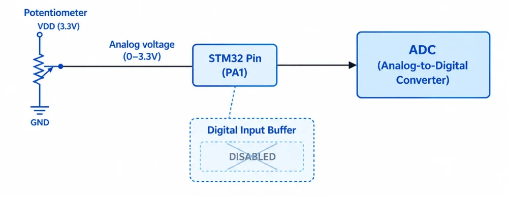
In Analog mode, the digital input and output circuitry on the pin is disabled or minimized, as appropriate for the pin.
This mode is used mainly for ADC and DAC related functions. When a pin carries an analog voltage into the ADC, the digital circuitry must not interfere with that signal by interpreting it as a High or Low logic level.
Analog mode provides two benefits:
- It reduces unwanted digital behavior, since the digital input buffer is no longer active and cannot introduce noise or false triggering.
- It helps reduce power consumption, since a digital input buffer can draw current when the input voltage is near its switching threshold.
If a pin connected to an analog source is left in Input mode instead of Analog mode, it may still produce readings. However, these readings can be noisier, and the pin will draw unnecessary power.
How GPIO Mode Selection Works
STM32 determines a pin’s mode using dedicated configuration registers. Each pin is assigned a fixed set of bits within these registers.
For STM32 families using the common GPIO architecture, the relationship works as follows:
- Each pin has a small, dedicated set of bits within the mode register.
- A specific bit pattern is written into these bits.
- This bit pattern determines which of the four modes the pin operates in.
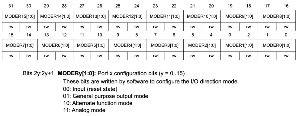
Additional registers typically control related settings, such as pull-up or pull-down selection, output type (push-pull or open-drain), output speed, and the specific alternate function selected when a pin is in Alternate Function mode.
Configuring GPIO Modes in CubeMX
Most STM32 projects configure GPIO through CubeMX rather than by writing register values directly. It is still useful to understand what CubeMX generates, since this understanding is often needed when debugging.
The configuration flow is shown below.
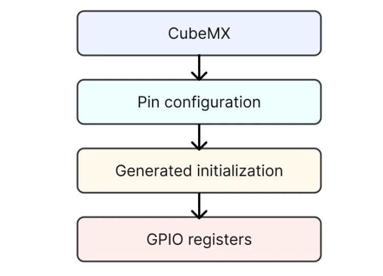
When a pin’s mode is selected in CubeMX, it generates the initialization code, typically inside a function such as MX_GPIO_Init(). This generated code writes to the same configuration registers described in the previous section. CubeMX does not introduce new behavior, it performs the register configuration that would otherwise need to be written manually.
Reviewing the generated .c file is a useful way to confirm what CubeMX has configured. The GPIO initialization structure typically includes fields such as Pin, Mode, Pull, and Speed, which correspond directly to the register bits described earlier. Comparing this generated code against the conceptual register configuration is a reliable way to verify a pin’s setup, and is a useful habit when a peripheral is not behaving as expected.
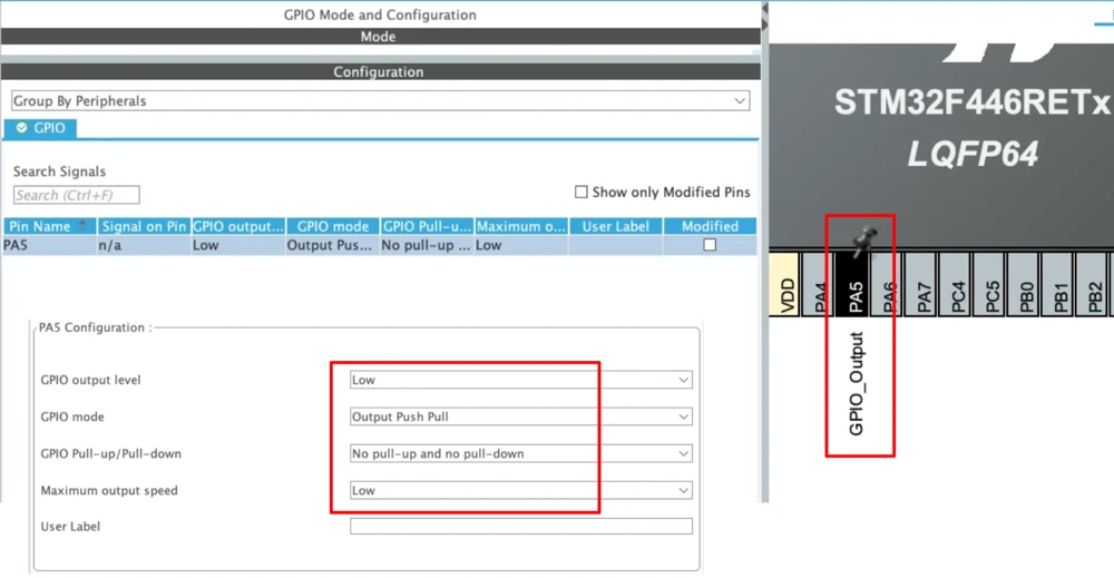
Here’s an example of generated code for a pin configured in Output mode:
|
1 2 3 4 5 6 7 8 9 10 11 12 13 14 15 16 17 |
static void MX_GPIO_Init(void) { GPIO_InitTypeDef GPIO_InitStruct = {0}; /* GPIO Ports Clock Enable */ __HAL_RCC_GPIOA_CLK_ENABLE(); /*Configure GPIO pin Output Level */ HAL_GPIO_WritePin(GPIOA, GPIO_PIN_5, GPIO_PIN_RESET); /*Configure GPIO pin : PA5 */ GPIO_InitStruct.Pin = GPIO_PIN_5; GPIO_InitStruct.Mode = GPIO_MODE_OUTPUT_PP; GPIO_InitStruct.Pull = GPIO_NOPULL; GPIO_InitStruct.Speed = GPIO_SPEED_FREQ_LOW; HAL_GPIO_Init(GPIOA, &GPIO_InitStruct); } |
When to Use Each GPIO Mode
The table below summarizes the appropriate mode for common requirements.
| Requirement | GPIO Mode |
|---|---|
| Read button | Input |
| Drive LED | Output |
| UART TX | Alternate Function |
| SPI clock | Alternate Function |
| Timer PWM | Alternate Function |
| ADC input | Analog |
As a general rule: if the pin is reading a signal, use Input. If the microcontroller is driving the signal directly, use Output. If a peripheral is generating the signal, use Alternate Function. If the pin carries an analog voltage, use Analog.
Conclusion
GPIO mode configuration comes down to one question: what function is this pin performing. Once this is clearly established for every pin, whether Input, Output, Alternate Function, or Analog, the rest of the GPIO setup becomes straightforward.
It is common to confuse Output and Alternate Function modes at least once before the distinction becomes clear, usually the first time a UART or PWM pin is left in plain output mode by mistake. Going back through the requirement table above, and checking each pin’s mode against what it is actually meant to do, is a reliable way to catch this early.
In the next tutorial, we will look at GPIO speed settings, and why they matter more than most beginners expect.