STM32 HAL vs LL: What’s the Difference?
You start a fresh STM32 project and want to do something as simple as blinking an LED. So, naturally, you search online for how to do it. That’s when things get confusing. You find three completely different approaches.
One person uses HAL_GPIO_TogglePin(). Another uses LL_GPIO_TogglePin(). And a third goes directly to the hardware register with GPIOA->ODR ^= (1<<5);.
All three can blink the same LED, but why are there three different ways to do the same thing?
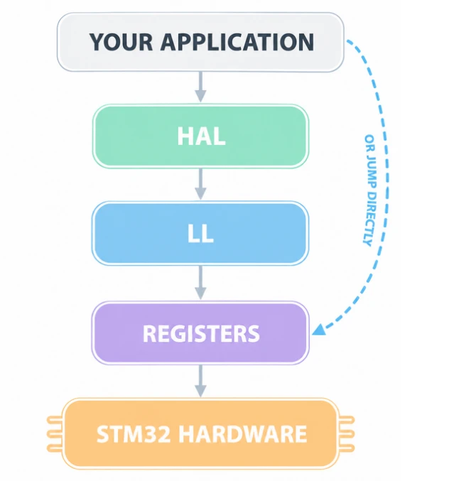
That is what this tutorial is about. STM32 lets you control the same hardware from three different heights. You can sit high up and let ST’s code do the work. You can sit lower and write something close to the hardware. Or you can go all the way down and control the registers yourself.
None of these is “the correct way.” They are just different trade-offs. By the end of this post you will know exactly which one to pick and why. We will keep it simple. We will use one tiny example — turning a GPIO pin on and off — and write it using different ways.
Table of contents
How STM32 Software Controls Hardware
Before we compare anything, let’s understand few things. The STM32 chip does not understand C. It does not know what HAL_GPIO_TogglePin means. It does not know what a library is. It only understands one thing, Memory writes.
Inside an STM32, there are millions of tiny electronic switches (transistors). A switch to turn on a GPIO port. A switch to set a pin as output. A switch to drive that pin high. Each of these switches is a bit sitting at a fixed memory address. Those memory addresses are called registers.
When you write a value to a register address, the hardware reacts instantly. Write a 1 to the correct bit and the pin goes high. Write a 0 and it goes low. That is the entire logic.
So every single method we talk about today ends up doing the same thing. Every one of them eventually writes to a register. The difference is only how much code runs before that write happens.
- With registers, there is nothing in between. We write the bit ourself.
- With LL, there is a thin layer. It gives the bit a readable name, but the code still ends up as a single register write.
- With HAL, there is a thick layer. It checks our inputs, tracks the state of the peripheral, handles errors, and then writes the register for us.
That’s the whole difference. Same hardware, same ending, different amount of code in the middle.
What is STM32 HAL?
HAL stands for Hardware Abstraction Layer. It is a big C library written by ST. It comes free with STM32CubeIDE and CubeMX. When you create a project in CubeMX and click “Generate Code”, HAL is what you get by default.
The idea behind HAL is simple. ST wanted your code to work on any STM32 chip. So they hid all the chip-specific details behind friendly function names.
Here is what that looks like in practice.
|
1 |
HAL_GPIO_WritePin(GPIOA, GPIO_PIN_5, GPIO_PIN_SET); |
You don’t need to know which register holds the output bit, or the bit position for pin 5. You don’t even need to open the reference manual. The function name tells you what it does.
HAL works the same way for every peripheral. UART, SPI, I2C, timers, ADC — they all follow the same pattern:
|
1 2 3 |
HAL_UART_Transmit(&huart2, data, 10, 100); HAL_SPI_Transmit(&hspi1, data, 10, 100); HAL_I2C_Master_Transmit(&hi2c1, addr, data, 10, 100); |
What HAL does
HAL is not just a wrapper. It actually handles a lot of work behind the scenes.
- It checks the inputs. HAL functions run assert_param() checks to catch bad arguments.
- It tracks state. Every peripheral has a handle struct like huart2. HAL uses it to remember if the peripheral is busy, ready or in error.
- It handles timeouts. When we use HAL to send UART data, it will give up after a timeout instead of hanging forever.
- It gives the callbacks. It uses functions like HAL_UART_RxCpltCallback() to handle the interrupt. We just need to fill in the body.
- It manages DMA. Functions like HAL_UART_Receive_DMA() set up the DMA stream, the interrupts and the flags in one line.
That is a lot of value for free. This is why HAL is the default for most projects.
The cost of HAL
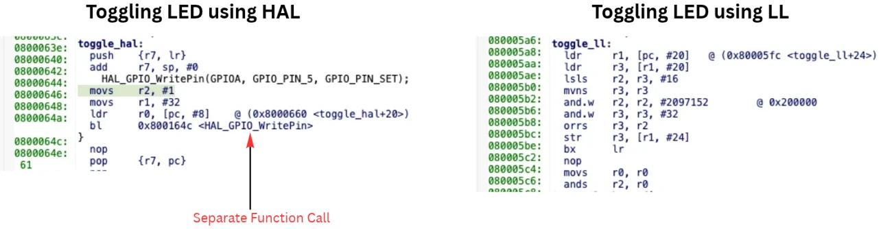
All that help is written in C code, and that code has to run somewhere. A single HAL_GPIO_WritePin() call is a real function call — it pushes arguments, jumps into the function, runs a few safety checks, writes the register, and then returns. Out of all that, the actual register write is just one instruction. Everything else around it is overhead.
For blinking an LED, none of this matters. But toggle a pin inside a 1 MHz interrupt, and suddenly that overhead is the whole problem.
HAL also pulls in a fair amount of code along with it. Every HAL module you enable adds a few more kilobytes to your flash. On a big STM32F4 with 512 KB of flash, you’ll never notice, but it matters a lot on a tiny STM32C0 with just 16 KB flash.
What is STM32 LL?
LL stands for Low Layer. It’s also written by ST and ships with STM32Cube, but it was built with the opposite goal in mind. HAL was designed to answer one question: how do you make this easy and portable? LL was designed to answer a completely different one: how do you make this small and fast?
Most LL functions are static inline, which means the compiler pastes the code straight into your function instead of calling out to it. There’s no jump, no stack push, no return — the function call disappears entirely at compile time.
Here’s an LL call:
|
1 |
LL_GPIO_SetOutputPin(GPIOA, LL_GPIO_PIN_5); |
It looks a lot like HAL, right? But under the hood, this is literally all it becomes:
|
1 |
GPIOA->BSRR = LL_GPIO_PIN_5; |
One register write. That’s everything the compiler generates.
So LL gives you readable, memorable function names without paying for them at runtime. You still get code you can read and reason about, but the machine code that comes out the other end is just as tight as if you’d written the register yourself.
How LL is different from HAL
LL takes a very different approach than HAL, and it shows in almost every design decision.
There’s no handle struct to manage. You work with the peripheral pointer directly, which means there’s no hspi1 to initialize, configure, and keep track of throughout your program. There’s also no state tracking behind the scenes — if you try to send UART data while the line is still busy, LL simply lets you. It has no concept of “busy” in the first place, so making sure the peripheral is actually ready is entirely your responsibility now.
The same logic applies to timeouts and interrupts. If you need to wait on a status flag, you write that wait loop yourself, since LL won’t do it for you. And when an interrupt fires, you’re writing the handler from scratch and clearing the flags manually, rather than relying on a callback that’s already wired up.
None of this makes LL harder to use in a bad way — it just means LL assumes you already understand how the peripheral works at a register level. You’ll find yourself reaching for the reference manual noticeably more often than you would with HAL, simply because LL isn’t going to explain anything on your behalf.
In practice, this makes LL a thin, well-named layer that sits directly on top of the registers. It gives you readable function names instead of raw bit manipulation, but beyond that, it doesn’t try to do much else.
LL init functions
That said, LL does ship a handful of heavier helper functions as well, such as LL_GPIO_Init() and LL_USART_Init(), which take a configuration struct in much the same way their HAL equivalents do.
These functions aren’t inline, so they behave more like traditional function calls and do cost a bit of flash. In practice, though, that cost rarely matters — they’re typically used once during startup, where a few extra bytes or cycles make no real difference to your application.
If you’d rather not include them at all, you don’t have to. Setting USE_FULL_LL_DRIVER to off in your project strips these heavier functions out entirely, leaving you with only the lightweight inline functions that make LL what it is.
What is Register-Level Programming?
This is the bottom floor — there’s no ST library involved at all.
Instead, you write directly to the peripheral registers using the CMSIS header files. These headers still come from ST, but they only define things — struct layouts, memory addresses, and bit masks. There’s no function logic hiding inside them, just the raw definitions your code builds on.
|
1 |
GPIOA->BSRR = (1U << 5); |
That’s the entire operation. One line, and it compiles down to a single store instruction. This style of programming is often called bare metal, and you’ll frequently hear it described the same way: no HAL, no LL, just registers.
Why anyone does this
The biggest draw is speed — this is about as fast as code can get, since there’s genuinely nothing standing between you and the hardware. It’s also the smallest code you’ll ever write for a given task, with zero library overhead pulling in extra flash.
There’s an honesty to it too. Every bit that gets set is one you set yourself, so when something breaks, the cause is sitting right there in front of you rather than buried inside someone else’s library.
But if you ask most experienced developers, they’ll point to a different reason entirely — it’s simply the best way to learn how the chip actually works. Every beginner should write at least one GPIO driver this way. Once you’ve flipped a pin using nothing but registers, HAL suddenly stops feeling like magic and starts making sense.
Why most people don’t do this everywhere
The trade-off is that you’re constantly living in the reference manual. Which bit of MODER sets output mode? Which register actually enables the clock? These aren’t things you memorize — they’re things you look up, over and over, in a document that easily runs past 1500 pages.
That dependency on the manual also makes it easy to get things wrong. Forget to enable the GPIO clock, for instance, and your writes simply do nothing — no error, no warning, just a pin that refuses to move while you wonder what’s going on.
Portability takes a hit as well. Register names and bit layouts aren’t consistent across STM32 families, so code written for an F4 might not even build on a G0 without changes.
And on top of all that, it’s just slow to write. Setting up a USART by hand with registers can take hours, while CubeMX gets you the same result through HAL in about two minutes.
That combination is exactly why most real projects don’t rely on registers for everything. Instead, they save this level of control for the handful of spots where speed genuinely matters.
HAL vs LL vs Registers
With all three explained, let’s compare them:
| HAL | LL | Registers | |
|---|---|---|---|
| Written by | ST | ST | You |
| Ease of use | Easiest | Medium | Hardest |
| Speed | Slowest | Near-native | Fastest |
| Flash size | Largest | Small | Smallest |
| Portable across STM32 | Yes | Mostly | No |
| CubeMX support | Full | Full | None |
| Reference manual needed | Rarely | Often | Always |
| Handles DMA and IRQ for you | Yes | No | No |
| Error checking | Yes | Minimal | None |
| Best for | Most projects | Tight loops, small chips | Learning, critical paths |
One thing worth noticing here is how close LL sits to registers in both speed and size, while still being far easier to read and much harder to get wrong.
That combination is exactly why LL ends up being the sweet spot for a lot of developers. You get nearly all the performance of raw registers, without having to live in the reference manual to get there.
The Same GPIO Operation Three Ways
This section puts the theory into code. The goal is to configure PA5 as a push-pull output and toggle it. PA5 is the user LED on most Nucleo boards, so the result can be seen directly on hardware.
The examples target an STM32F4, but the logic is the same across other families, only some register names differ.
Version 1 — HAL
|
1 2 3 4 5 6 7 8 9 10 11 12 13 14 15 16 17 |
/* Enable the clock for GPIO port A */ __HAL_RCC_GPIOA_CLK_ENABLE(); /* Configure PA5 as push-pull output */ GPIO_InitTypeDef GPIO_InitStruct = {0}; GPIO_InitStruct.Pin = GPIO_PIN_5; GPIO_InitStruct.Mode = GPIO_MODE_OUTPUT_PP; GPIO_InitStruct.Pull = GPIO_NOPULL; GPIO_InitStruct.Speed = GPIO_SPEED_FREQ_LOW; HAL_GPIO_Init(GPIOA, &GPIO_InitStruct); /* Use the pin */ while (1) { HAL_GPIO_TogglePin(GPIOA, GPIO_PIN_5); HAL_Delay(500); } |
The code reads close to plain English: enable the clock, fill a struct, initialize, toggle. No register name appears anywhere, and no bit position needs to be looked up. If the project was generated through CubeMX, the initialization block is already written.
This readability is the main reason HAL is the default choice for most projects.
Version 2 — LL
|
1 2 3 4 5 6 7 8 9 10 11 12 13 14 15 16 17 18 |
/* Enable the clock for GPIO port A */ LL_AHB1_GRP1_EnableClock(LL_AHB1_GRP1_PERIPH_GPIOA); /* Configure PA5 as push-pull output */ LL_GPIO_InitTypeDef GPIO_InitStruct = {0}; GPIO_InitStruct.Pin = LL_GPIO_PIN_5; GPIO_InitStruct.Mode = LL_GPIO_MODE_OUTPUT; GPIO_InitStruct.OutputType = LL_GPIO_OUTPUT_PUSHPULL; GPIO_InitStruct.Speed = LL_GPIO_SPEED_FREQ_LOW; GPIO_InitStruct.Pull = LL_GPIO_PULL_NO; LL_GPIO_Init(GPIOA, &GPIO_InitStruct); /* Use the pin */ while (1) { LL_GPIO_TogglePin(GPIOA, LL_GPIO_PIN_5); delay_ms(500); } |
The setup closely mirrors HAL, since LL_GPIO_Init() is one of the heavier helper functions described earlier.
The difference appears inside the loop. LL_GPIO_TogglePin() is inline, so the compiler reduces it to a read of ODR, an XOR, and a write back to ODR. No function call remains in the final binary.
The init helper can also be skipped, with the setup written using inline calls only:
|
1 2 3 4 5 6 |
LL_AHB1_GRP1_EnableClock(LL_AHB1_GRP1_PERIPH_GPIOA); LL_GPIO_SetPinMode(GPIOA, LL_GPIO_PIN_5, LL_GPIO_MODE_OUTPUT); LL_GPIO_SetPinOutputType(GPIOA, LL_GPIO_PIN_5, LL_GPIO_OUTPUT_PUSHPULL); LL_GPIO_SetPinSpeed(GPIOA, LL_GPIO_PIN_5, LL_GPIO_SPEED_FREQ_LOW); LL_GPIO_SetPinPull(GPIOA, LL_GPIO_PIN_5, LL_GPIO_PULL_NO); |
This version is fully inline — no struct, no function call, and minimal generated code.
For setting or clearing a pin rather than toggling it, these functions are used instead:
|
1 2 |
LL_GPIO_SetOutputPin(GPIOA, LL_GPIO_PIN_5); /* PA5 high */ LL_GPIO_ResetOutputPin(GPIOA, LL_GPIO_PIN_5); /* PA5 low */ |
Both compile down to a single register write to BSRR.
Version 3 — Registers
|
1 2 3 4 5 6 7 8 9 10 11 12 13 14 15 16 17 18 19 20 21 22 |
/* 1. Enable the clock for GPIO port A */ RCC->AHB1ENR |= RCC_AHB1ENR_GPIOAEN; /* 2. Set PA5 as general purpose output (MODER5 = 01) */ GPIOA->MODER &= ~(3U << (5 * 2)); /* clear both bits */ GPIOA->MODER |= (1U << (5 * 2)); /* set to 01 */ /* 3. Push-pull output (OT5 = 0) */ GPIOA->OTYPER &= ~(1U << 5); /* 4. Low speed (OSPEEDR5 = 00) */ GPIOA->OSPEEDR &= ~(3U << (5 * 2)); /* 5. No pull-up, no pull-down (PUPDR5 = 00) */ GPIOA->PUPDR &= ~(3U << (5 * 2)); /* 6. Use the pin */ while (1) { GPIOA->ODR ^= (1U << 5); delay_ms(500); } |
Every bit involved in this configuration is now visible. Each register is explained below.
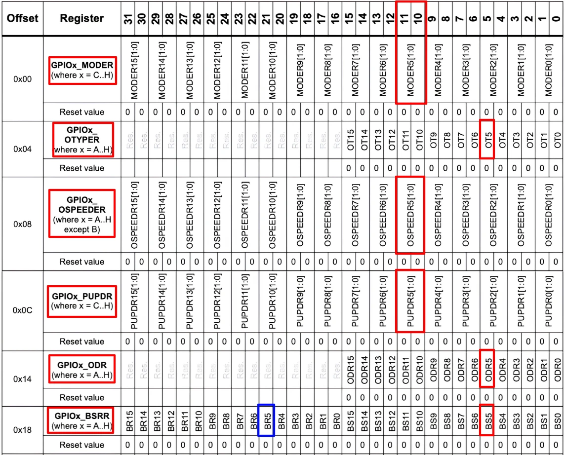
- The clock. RCC->AHB1ENR enables the clock for each port on the AHB1 bus. Without this line, the rest of the code has no effect, and no error is raised. This is the most common mistake in bare-metal GPIO code.
- MODER. This register uses two bits per pin: 00 for input, 01 for output, 10 for alternate function, and 11 for analog. Pin 5 occupies bits 10 and 11, reached by shifting 5 * 2. Both bits are cleared first, then set to the required value.
- OTYPER. One bit per pin: for push-pull, 1 for open-drain.
- OSPEEDR. Two bits per pin, controlling edge speed. Higher speed produces faster transitions and more electrical noise. Low speed is sufficient for an LED.
- PUPDR. Two bits per pin. 00 disables the pull resistor, which is appropriate here since the output driving the LED does not need one.
- ODR. The output data register. The XOR operation flips the bit.
The better way to set a pin
ODR works for toggling, but BSRR is the better choice for setting or clearing a pin:
|
1 2 |
GPIOA->BSRR = (1U << 5); /* set PA5 high */ GPIOA->BSRR = (1U << (5 + 16)); /* set PA5 low */ |
The reason is that ODR ^= x is actually three separate operations: a read, a modify, and a write. If an interrupt occurs between these steps and changes a different pin on the same port, the subsequent write can overwrite that change.
BSRR avoids this. It performs a single atomic write, where the lower 16 bits set pins and the upper 16 bits clear them; any untouched bits are left unaffected. This makes it safe to use even in interrupt-heavy code.
LL_GPIO_SetOutputPin() and HAL_GPIO_WritePin() use BSRR internally for this exact reason.
When Should You Use HAL, LL or Registers?
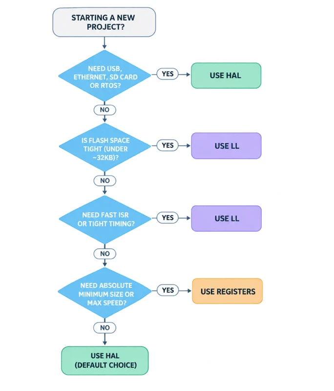
This section lays out practical guidance for choosing between the three.
Use HAL when
- Getting started with STM32 and aiming to have something running quickly
- Building a prototype where development speed matters more than execution speed
- The project needs USB, Ethernet, SD card support, or FreeRTOS middleware, since these are all built on top of HAL
- The code needs to run across more than one STM32 family
- The team has mixed experience levels, where readable code matters more than saved cycles
- Flash and RAM are not tightly constrained
HAL is the right choice for the majority of real projects — a rough estimate would put this at around 80%. Choosing HAL is not a compromise, it is simply the appropriate tool for most use cases.
Use LL when
- Working on a small chip where flash space is limited
- Optimizing for a fast ISR, a bit-banged protocol, or a tight control loop
- Needing to know exactly what the code does without referring to a reference manual
- Building a low-power design, where every wasted cycle affects battery life
- HAL’s API does not expose a feature that is needed
LL tends to be overlooked. Many developers skip it entirely and jump straight from HAL to registers, which is usually an unnecessary step — LL often solves the same problem with far less effort.
Use registers when
- Learning how the underlying hardware actually works; this is worth doing at least once
- Absolute minimum code size is required, such as in a bootloader that must fit within a few kilobytes
- The fastest possible response time is needed inside an interrupt
- Debugging an issue that requires inspecting the real register values directly
- Zero third-party code is required in a safety-critical path
Start with HAL. Move to LL where performance requires it. Move to registers only where LL still isn’t enough.
Can HAL and LL Be Used Together?
Yes, and this is often the part that surprises people most. All three approaches can be mixed within the same project, the same file, and even the same function.
This works because every layer ultimately ends up writing to the same registers. There is no hidden mechanism that causes a conflict, and LL does not “lock” a peripheral away from HAL in any way.
How to enable both in CubeMX
In CubeMX, this is configured under Project Manager → Advanced Settings, where a list of peripherals is shown. Each peripheral has its own driver dropdown, set to either HAL or LL.
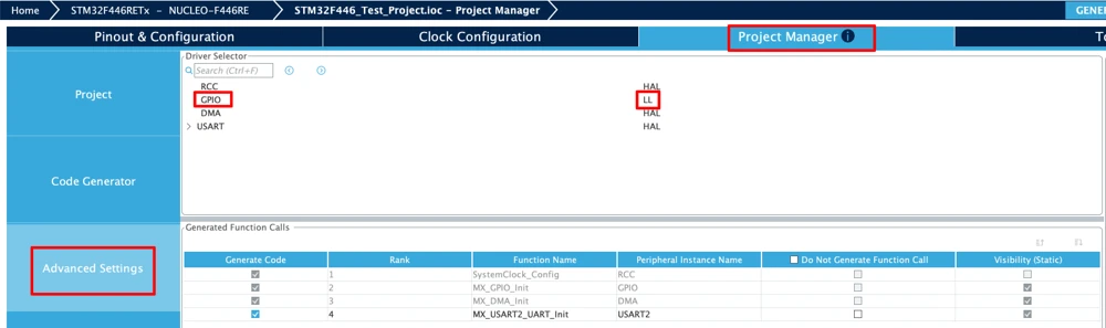
Setting GPIO to LL while leaving UART on HAL, then generating the code, works without issue. Both sets of headers are included, and both drivers function correctly side by side.
A mixed example
Consider a project that reads sensor data over UART while also driving a fast PWM-style pattern on a GPIO pin.
|
1 2 3 4 5 6 7 8 9 10 11 12 13 |
/* Setup done by HAL — easy and only runs once */ MX_GPIO_Init(); MX_USART2_UART_Init(); /* Slow, non-critical work uses HAL */ HAL_UART_Transmit(&huart2, msg, len, 100); /* Fast bit-banging inside an ISR uses LL */ void TIM2_IRQHandler(void) { LL_GPIO_TogglePin(GPIOA, LL_GPIO_PIN_5); LL_TIM_ClearFlag_UPDATE(TIM2); } |
This pattern is both common and sensible: HAL handles setup and non-critical work, while LL is reserved for the fast path.
One warning
HAL and LL should not be mixed on the same peripheral during runtime. HAL relies on its handle struct to track peripheral state. If a UART register is modified directly through LL, that handle no longer reflects reality — HAL may then assume the port is free when it is actually busy, or the reverse.
For GPIO, this is generally safe, since HAL’s GPIO driver tracks very little state to begin with. For UART, SPI, I2C, and DMA, however, one driver should be chosen per peripheral and used consistently.
Registers on top
Raw register access can also be added anywhere, even within a fully HAL-based project:
|
1 2 |
MX_GPIO_Init(); /* HAL setup */ GPIOA->BSRR = (1U << 5); /* raw register write */ |
This is entirely valid. The same caution applies here as well — avoid working against a HAL driver that still assumes it owns the peripheral.
Practical Decision Guide
The table below summarizes the guidance covered so far and can serve as a quick reference.
| Situation | Recommended approach |
|---|---|
| First STM32 project | HAL |
| Learning how the chip works | Registers, then HAL |
| Blinking an LED, reading a button | HAL |
| USB, Ethernet, SD card, FreeRTOS | HAL |
| Chip with under 32 KB flash | LL |
| Toggling a pin inside a fast ISR | LL or registers |
| Bit-banging a custom protocol | LL or registers |
| Battery-powered, every cycle counts | LL |
| Writing a small bootloader | Registers |
| HAL doesn’t expose the feature needed | LL or registers |
| Porting code between STM32 families | HAL |
| Job interview asks “how does GPIO work?” | Registers |
Conclusion
HAL, LL and registers are not three separate technologies — they represent three different distances from the same underlying hardware. Each one ultimately ends with a value being written to a register. HAL simply takes more code to get there, LL takes very little, and registers take none at all.
HAL is the approachable option. It is portable, readable, and largely generated for you through CubeMX. The trade-off is flash usage and execution cycles, though for most projects that cost is negligible — which is exactly why HAL remains the sensible starting point.
LL occupies the middle ground and is arguably the most underused of the three. It delivers register-level performance while keeping function names readable. When HAL turns out to be too slow or too large for a given task, LL — not raw registers — should usually be the next step.
Registers represent the most direct view of the hardware. Nothing is hidden, assumed, or added unnecessarily. They take longer to write and are easier to get wrong, but working through a GPIO driver by hand at least once builds a stronger understanding of STM32 than any amount of HAL example code alone.