STM32 Pull-Up and Pull-Down Resistors
A digital input on an STM32 is expected to see either a clear HIGH or a clear LOW. In a real circuit, however, an input pin is often connected to something that drives the line only part of the time, such as a push button, a mechanical switch, or the open-drain output of another chip. During the moments when nothing drives the line, the pin has no defined voltage, and the value software reads from it becomes unpredictable.
This article explains how pull-up and pull-down resistors solve that problem. We will start with the reason why inputs float. Then look at how each type of resistor sets a default level, compare the STM32 inbuilt resistors with external ones, and understand active-low and active-high inputs. The second half will cover how to choose the pull setting in CubeMX and build a working button example on a NUCLEO-F446RE board.
This article is part of the STM32 GPIO tutorial series.
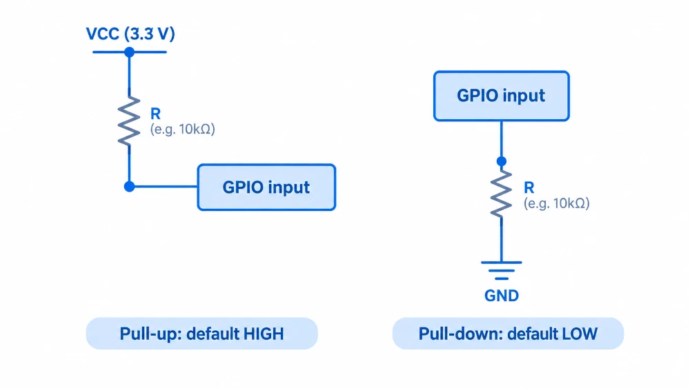
Table of contents
Why Do GPIO Inputs Float?
A GPIO pin that is configured as an input does not drive anything. Its only job is to measure the voltage that appears at the pin. Internally, the pin connects to the input of a Schmitt trigger, which is a buffer that turns the analog voltage into a clean digital value. The Schmitt trigger has two thresholds, one for a rising signal and one for a falling signal, and the output changes only when the voltage crosses the relevant threshold. The value that the software reads through HAL_GPIO_ReadPin() comes from the output of this buffer.
The input of the buffer has a very high impedance, which means that it draws almost no current from the pin. That property is useful when the pin is connected to a proper signal source, but it causes a problem when the pin is connected to nothing at all. A pin with no defined source has no path that would hold its voltage at any particular level, so a very small amount of charge is enough to move it. Small interferences, such as nearby signal traces, a hand touching the board, or a loose jumper wire acting as an antenna for mains noise can cause fluctuations in pin voltage. This condition is called a floating input.
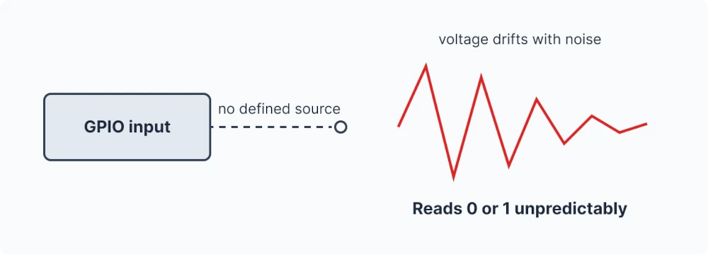
This result in a reading that can change in a moment, even though the software and the hardware have not changed. When the voltage drifts between the two Schmitt trigger thresholds, the value can flip back and forth, and the input buffer can also draw a little more supply current than it normally would. A floating pin is therefore both a source of random behavior and a small waste of power.
Floating does not only happen with pins that are left unconnected. A push button that connects the pin to ground when it is pressed leaves the pin unconnected while it is released. The same applies to the output of a device that stops driving its line, such as an open-drain output in its released state. In every one of these cases, something must hold the pin at a known level when the main source is inactive, and that is the job of a pull resistor.
What is a Pull-Up Resistor?
A pull-up resistor connects the input pin to the supply voltage through a resistor. When nothing else drives the pin, the input draws almost no current. So there is almost no voltage drop across the resistor, and the pin voltage settles very close to VCC. The software therefore reads a HIGH, which makes HIGH the default state of the line.
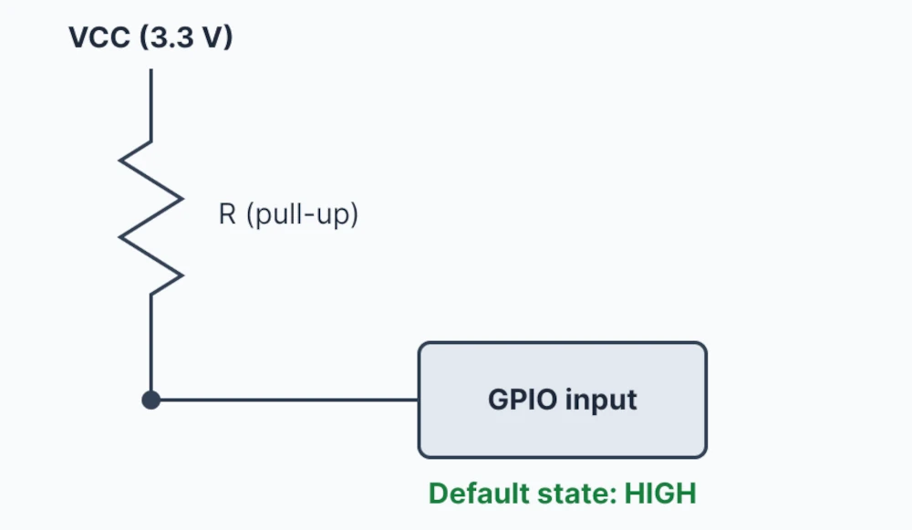
The word “pull” is chosen carefully, because the resistor pulls the line toward VCC only weekly. When a switch or another output connects the pin to ground, that connection is a much lower resistance than the pull-up, so the pin voltage drops to nearly 0 V and the reading becomes LOW. The resistor and the source together behave like a voltage divider, and the smaller resistance decides the outcome. This is why a pull-up can be overridden by any device that is able to drive the line, without any conflict.
The resistor also carries a small current whenever the line is held LOW, and that current equals the supply voltage divided by the resistance. For example, a 10 kΩ resistor on a 3.3 V supply draws about 330 µA while the line is pulled down, and a resistor four times larger draws about a quarter of that current. This relationship between resistance, current, and speed is the reason why the choice of resistor value matters.
What is a Pull-Down Resistor?
A pull-down resistor is the mirror image of a pull-up. It connects the input pin to ground through a resistor, so that a pin with no other source settles at nearly 0 V. The software reads a LOW, which makes LOW the default state of the line.
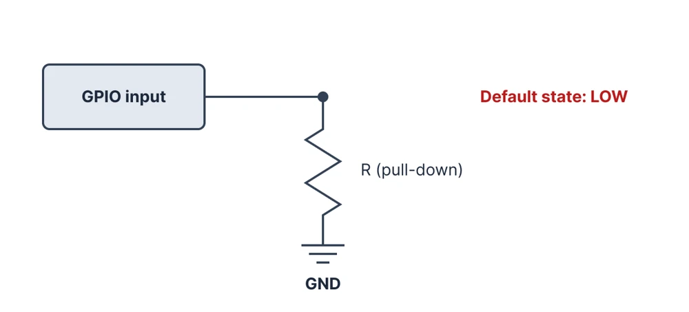
The pull-down works in the same way as the pull-up, with the polarity reversed. When another device drives the line HIGH, or when a switch connects the pin to VCC, that source overrides the resistor and the pin reads HIGH. When the source releases the line, the resistor drains the line back to ground, and the pin returns to LOW. A pull-down is the natural choice when the connected signal is active-high, meaning that the signal is HIGH when it is asserted and idle at LOW.
Both resistors solve the same underlying problem, which is that a high-impedance input needs a defined level at all times. The only real difference is the level that the line takes when nothing else is driving it.
Internal vs External Pull Resistors
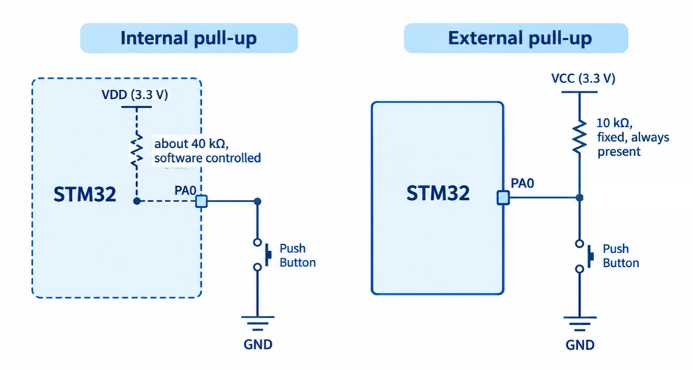
Every STM32 GPIO pin contains a built-in pull-up resistor and a built-in pull-down resistor, and each of them can be switched on or off in software. Only one of the two can be enabled on a pin at the same time. The value of these resistors depends on the device family. On the STM32F4 series that we use in this series, the datasheet lists a typical value of about 40 kΩ with a range from 30 kΩ to 50 kΩ. Other families use somewhat different values, so the electrical characteristics table in the datasheet of the specific chip is the place to confirm the number.
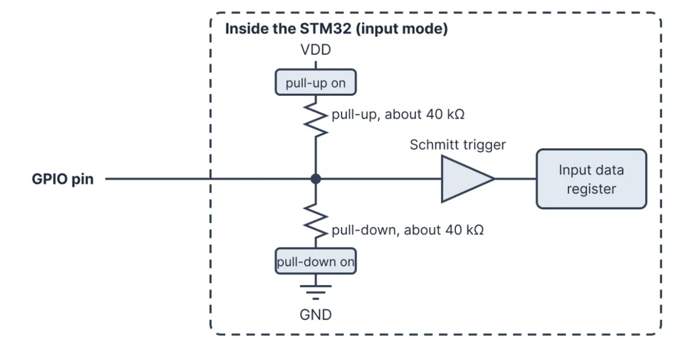
The internal resistors have clear advantages. They remove the need for an extra component, which saves board space and cost. Also they can be changed in software, which makes it easy to experiment or to reuse the same hardware for different purposes. An internal pull-up is usually enough for simple use cases, like a button connected for the input trigger.
The limitations come from the same design. A value of about 40 kΩ is a weak resistor, so it is easily overpowered by noise and by leakage currents. It also charges the wiring capacitance slowly, which limits the speed of the signal. The value is also not precise, since it varies with temperature and from one chip to another. In addition, the internal resistor exists only after the software has configured the pin. Most pins start in a floating input state after reset. Therefore during power-up, reset, and the time spent in the bootloader, the internal resistor cannot hold anything at a defined level.
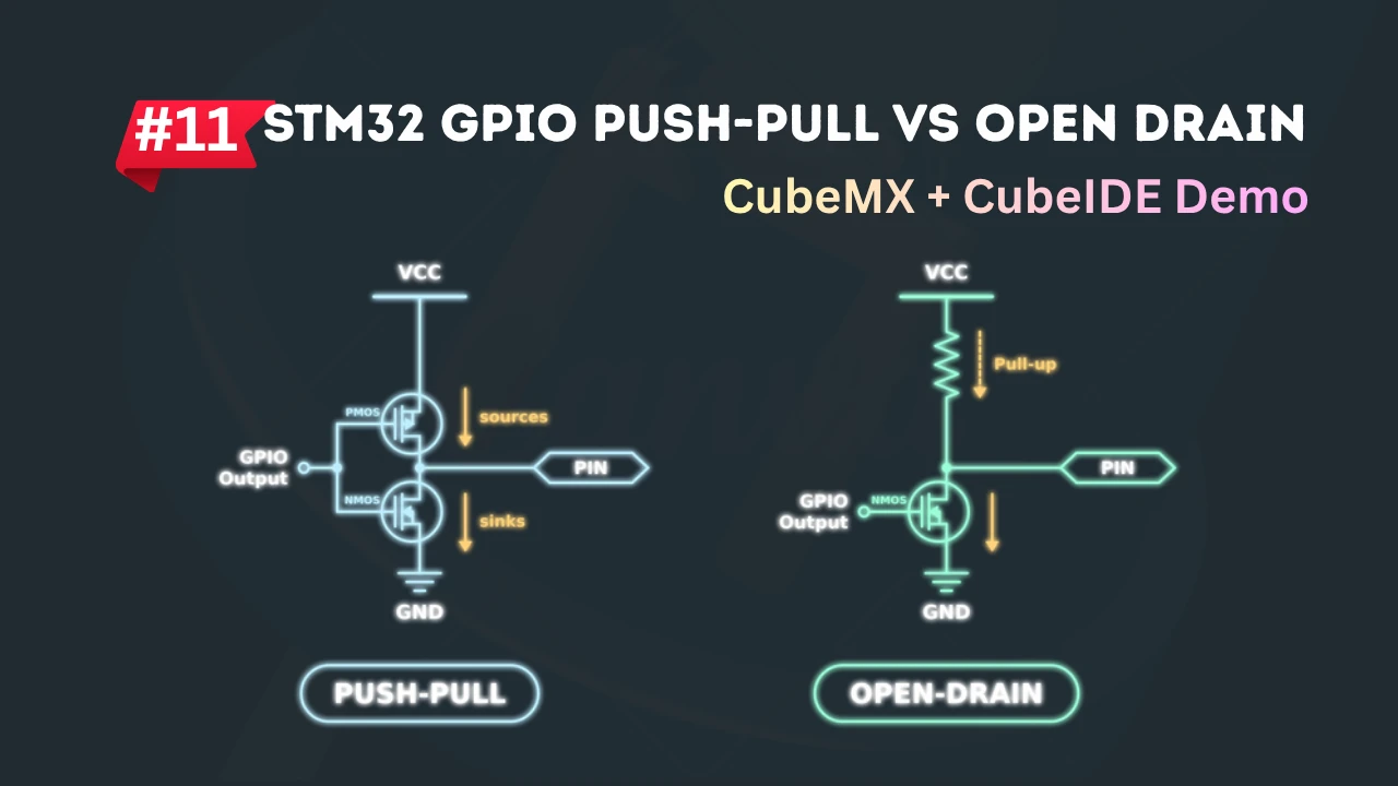
External resistors are the better choice in several situations. A line that must have a defined level before the firmware starts, such as a chip-select line for an external memory or an enable pin of a regulator, needs an external resistor, because the internal one is not yet active. Long cables and electrically noisy environments benefit from a lower resistance, since a lower resistance holds the line more firmly. Shared buses such as I²C also require external pull-ups with a value chosen for the bus speed, as explained in the STM32 GPIO Push-Pull vs Open-Drain.
Active-Low vs Active-High Inputs
A signal is called active-high when its asserted state is HIGH, and active-low when its asserted state is LOW. For a push button, the asserted state is the pressed state. An active-high button reads HIGH when it is pressed, and an active-low button reads LOW when it is pressed.
The two styles differ in where the switch connects and in which resistor holds the idle level. An active-high button connects the pin to VCC when pressed and needs a pull-down to hold the pin LOW while the button is released. Whereas, an active-low button connects the pin to ground when pressed and needs a pull-up to hold the pin HIGH while the button is released.
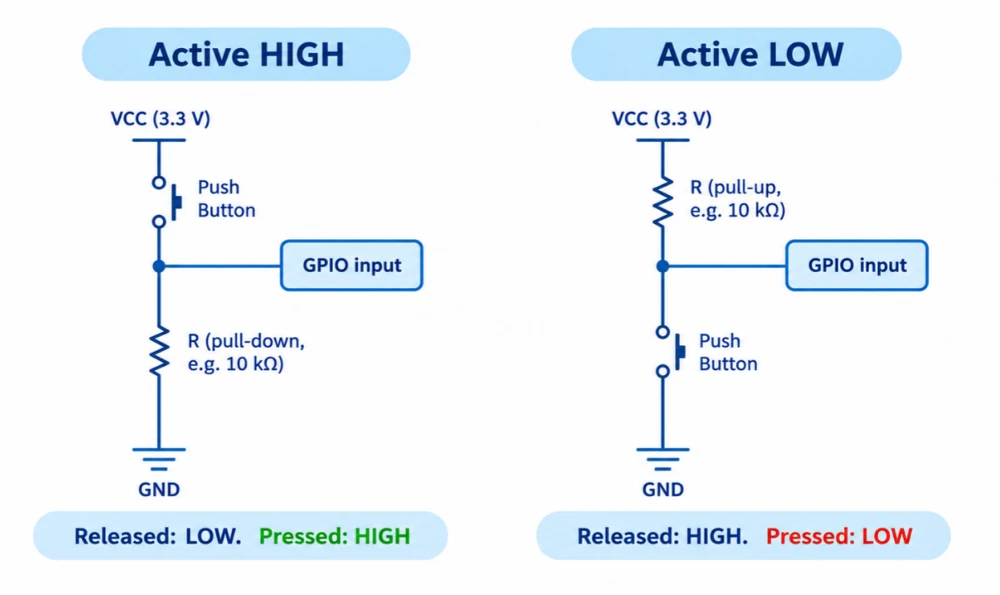
The active-low arrangement with a pull-up is far more common in practice, and there are several reasons for it. The switch connects to ground, which is available everywhere on a board, so a button needs only one signal wire and one ground connection. Nearly every microcontroller offers an internal pull-up, so the whole circuit can be built with just a button. The convention also matches the many active-low signals found on real chips, such as reset, chip select, and interrupt lines. Most of these come from open-drain outputs that can only pull the line down and therefore need a pull-up anyway.
Active-low inputs invert the logic in software, because a pressed button reads as GPIO_PIN_RESET and a released button reads as GPIO_PIN_SET. A good habit is to give the pressed state a clear name, such as a macro, so that the rest of the code does not have to remember which level means pressed.
|
1 2 3 4 5 6 7 |
#define BUTTON_PRESSED GPIO_PIN_RESET // active-low: pressed pulls the pin to GND #define BUTTON_RELEASED GPIO_PIN_SET if (HAL_GPIO_ReadPin(GPIOA, GPIO_PIN_0) == BUTTON_PRESSED) { HAL_GPIO_WritePin(GPIOA, GPIO_PIN_5, GPIO_PIN_SET); } |
STM32CubeMX Pull Settings
The pull setting in STM32CubeMX is part of the normal GPIO configuration, and it is configurable for any pin that is set as an input. The flow is the same in every project. We need to first set the pin as a GPIO input in the pinout view, and then choose the pull option in the GPIO configuration panel under System Core. If you are new to the CubeMX, read the STM32CubeMX Explained article first to understand it.
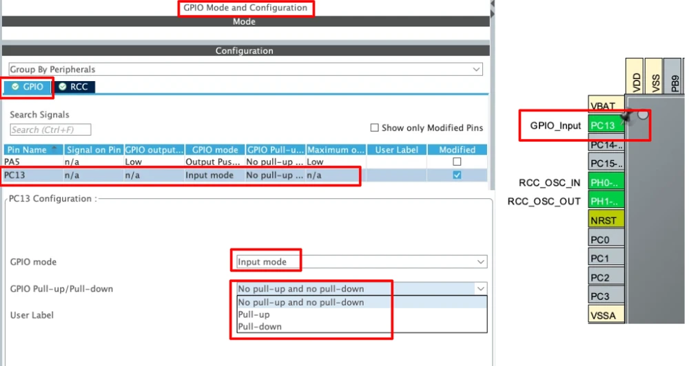
The three options in the drop-down list correspond to three HAL constants in the generated code, as the table below shows.
| CubeMX option | Generated constant | Meaning |
|---|---|---|
| No pull-up and no pull-down | GPIO_NOPULL | Both internal resistors off, so the pin floats unless an external source or resistor holds it |
| Pull-up | GPIO_PULLUP | Internal resistor to VDD enabled |
| Pull-down | GPIO_PULLDOWN | Internal resistor to GND enabled |
Note that the mode list for a plain GPIO input contains only the input mode, while the external interrupt modes appear when the pin is set as GPIO_EXTI instead. The pull option is available for both, so the same reasoning applies when a button is used with an interrupt.
STM32 Button Input Example
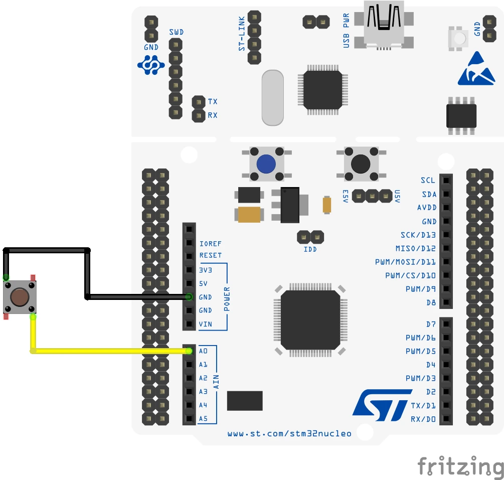
This example reads a push button that is wired between PA0 and ground, and it mirrors the state of the button on the green user LED of the board. The button uses the internal pull-up, so the pin reads HIGH while the button is released and LOW while it is pressed. The example uses the NUCLEO-F446RE, one push button along with two jumper wires, and the onboard LED on PA5.
This example uses an external button on PA0 instead of the onboard button on PC13, which is covered in the STM32 GPIO Complete Guide.
Step 1: Configure the Pins
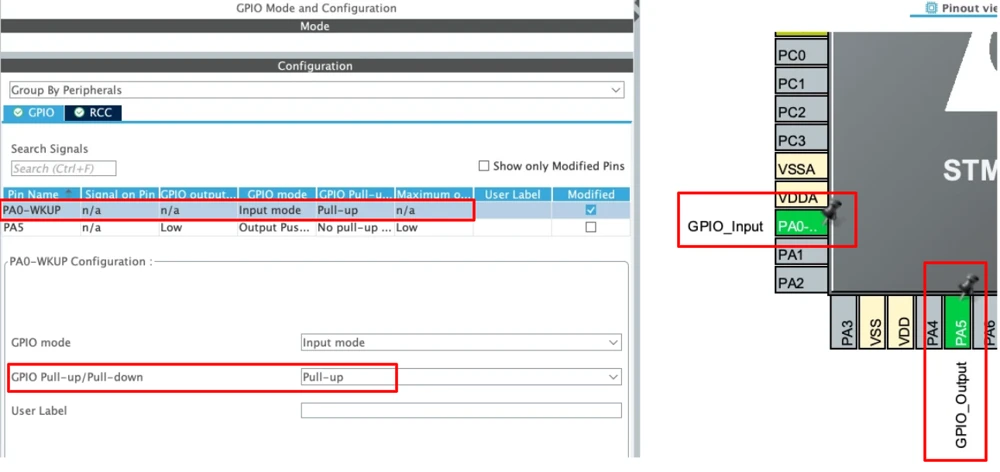
Create a new project for the NUCLEO-F446RE. In the Pinout & Configuration tab, click PA0 and choose GPIO_Input, then click PA5 and choose GPIO_Output. Open System Core → GPIO and set each pin as shown in the table.
| Setting | PA0 | PA5 |
|---|---|---|
| GPIO mode | Input mode | Output Push Pull |
| GPIO Pull-up/Pull-down | Pull-up | No pull-up and no pull-down |
| GPIO output level | Not applicable | Low |
| Maximum output speed | Not applicable | Low |
Step 2: The Generated Code
CubeMX writes the pin setup into MX_GPIO_Init() in main.c. The exact formatting varies a little between CubeMX versions.
|
1 2 3 4 5 6 7 8 9 10 11 12 13 14 15 16 17 18 |
/* GPIO Ports Clock Enable */ __HAL_RCC_GPIOA_CLK_ENABLE(); /*Configure GPIO pin Output Level */ HAL_GPIO_WritePin(GPIOA, GPIO_PIN_5, GPIO_PIN_RESET); /*Configure GPIO pin : PA0 */ GPIO_InitStruct.Pin = GPIO_PIN_0; GPIO_InitStruct.Mode = GPIO_MODE_INPUT; GPIO_InitStruct.Pull = GPIO_PULLUP; HAL_GPIO_Init(GPIOA, &GPIO_InitStruct); /*Configure GPIO pin : PA5 */ GPIO_InitStruct.Pin = GPIO_PIN_5; GPIO_InitStruct.Mode = GPIO_MODE_OUTPUT_PP; GPIO_InitStruct.Pull = GPIO_NOPULL; GPIO_InitStruct.Speed = GPIO_SPEED_FREQ_LOW; HAL_GPIO_Init(GPIOA, &GPIO_InitStruct); |
The line that matters for this article is GPIO_InitStruct.Pull = GPIO_PULLUP in the button block. An input pin does not use the speed field, so CubeMX does not generate one for PA0.
Step 3: Add the Application Code
In main.c, define the pressed state once so that the inverted logic has a clear name. Place this between the private-define markers.
|
1 2 3 |
/* USER CODE BEGIN PD */ #define BUTTON_PRESSED GPIO_PIN_RESET // active-low: pressed pulls the pin to GND /* USER CODE END PD */ |
Then add the loop body between the USER CODE BEGIN 3 markers.
|
1 2 3 4 5 6 7 8 9 10 11 12 13 14 15 16 |
while (1) { /* USER CODE END WHILE */ /* USER CODE BEGIN 3 */ if (HAL_GPIO_ReadPin(GPIOA, GPIO_PIN_0) == BUTTON_PRESSED) { HAL_GPIO_WritePin(GPIOA, GPIO_PIN_5, GPIO_PIN_SET); // LED on } else { HAL_GPIO_WritePin(GPIOA, GPIO_PIN_5, GPIO_PIN_RESET); // LED off } } /* USER CODE END 3 */ |
Keep all custom code between the USER CODE markers, or CubeMX will delete it the next time you regenerate the project.
Step 4: Build, Flash, and Test
Click Build and then Run. With the button released, the LED stays off, and a multimeter between PA0 and GND shows a voltage close to 3.3 V. Because the internal pull-up is weak, the meter itself loads the line a little, and the reading comes out slightly lower than 3.3 V. While the button is pressed, the LED turns on and the meter shows close to 0 V. The closed switch gives the pin a far easier path to ground than the 40 kΩ pull-up gives it toward VDD, so the pin reads LOW.
Step 5: Remove the Pull-Up
The control test shows what the pull resistor actually does. In CubeMX, select PA0 and change the pull setting to No pull-up and no pull-down, then regenerate the project. Only one line changes in the generated code.
|
1 |
GPIO_InitStruct.Pull = GPIO_NOPULL; // was GPIO_PULLUP |
Build and flash the project again, and leave the button released. The pin is now floating, so the LED may stay on, stay off, or flicker, and the state can change when you bring a finger close to the wire. Pressing the button still pulls the pin to ground, so the pressed state works as before.
To see the opposite polarity, set the pull to Pull-down and connect the other end of the button to the 3.3 V pin. The pin now idles LOW and goes HIGH when the button is pressed, so BUTTON_PRESSED must be changed to GPIO_PIN_SET.
When to Use Pull-Up or Pull-Down
The right choice depends on the idle state that the connected switch or device needs. A button that connects the pin to ground should be used with a pull-up, and a button that connects the pin to VCC should be used with a pull-down. Sensors and modules with a digital output follow the same logic. A module with an open-drain or open-collector output, such as many interrupt and alert pins, can only pull the line LOW, so it needs a pull-up to provide the HIGH level. A module with a push-pull output drives both HIGH and LOW actively, so it normally needs no pull resistor.
Control lines that connect to other chips need extra thought about what happens while the STM32 is still in reset. An active-low chip-select line usually gets a pull-up, so that the external device stays deselected during power-up. An active-high enable pin usually gets a pull-down, so that the external device stays switched off until the firmware turns it on. Both resistors should be external, because the internal resistors only become active after the firmware has configured the pins.
The table below describes the use cases for both types.
| Connected device or signal | What it does | Resistor | Internal or external |
|---|---|---|---|
| Button or switch to GND | Pulls the pin LOW when pressed | Pull-up | Internal is usually enough |
| Button or switch to VCC | Pulls the pin HIGH when pressed | Pull-down | Internal is usually enough |
| Open-drain or open-collector output (many interrupt and alert pins) | Can only pull the line LOW | Pull-up, to provide the HIGH level | Either, depending on the design |
| Push-pull output | Drives both HIGH and LOW actively | None normally needed | Not applicable |
| Active-low chip-select line to another chip | Asserted LOW | Pull-up, so the device stays deselected during power-up | External |
| Active-high enable pin on another chip | Asserted HIGH | Pull-down, so the device stays off until the firmware turns it on | External |
Conclusion
When nothing drives a GPIO input, the voltage at the pin is not defined, so the value that the software reads can change at random. A pull-up or pull-down resistor fixes this by holding the pin at a known default level, which is HIGH for a pull-up and LOW for a pull-down. The resistor is weak enough that a button or another device can still change the level whenever it needs to. Every STM32 GPIO pin has a built-in pull-up and pull-down resistors, and these are enough for simple cases. An external resistor is a better choice when the line must have a known level before the firmware starts, when the line is shared with other devices, or when noise or a long cable calls for a stronger resistor.
Active-low inputs with a pull-up are the most common pattern, because the button connects to ground and needs no extra parts. The software must then treat a LOW reading as pressed.
Download the Project Here
Download the CubeMX project files and HAL source code — all tested on real hardware.
If you find this useful, you can support us with a Donation as well.