STM32CubeMX Explained: What Is It and Why Use It?
If you have ever opened an STM32 reference manual and tried to configure a clock tree or a set of GPIO pins by writing directly to registers, you already know how much time that can take. Every peripheral has its own set of registers, and every register has its own rules about what values are allowed and in what order they need to be written. Getting this right by hand is possible, but it is slow, and it is easy to make a small mistake that costs hours of debugging later.
STM32CubeMX exists to remove most of that manual work. It is a graphical configuration tool from STMicroelectronics that lets you set up your microcontroller’s pins, clocks, and peripherals through a visual interface, and then generates the initialization code for you. Instead of writing register values from scratch, you configure what you want, and CubeMX writes the code that makes it happen.
This guide walks through what STM32CubeMX does, how to create a new project in it, and how to configure the pieces most projects need: pinout, GPIO, clocks, peripherals, interrupts, and DMA. We will also work through a simple hands-on example, generate a project, and take a look at what CubeMX actually produces.
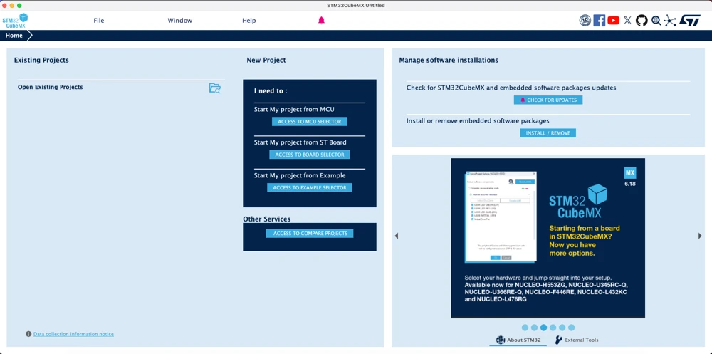
Table of contents
What Is STM32CubeMX?
STM32CubeMX is a free graphical tool from STMicroelectronics that helps you configure an STM32 microcontroller and generate the C code needed to initialize it. Rather than looking up register addresses and bit fields in a reference manual, you work with a visual representation of the chip. You click on pins to assign them, pick a clock source from a diagram of the clock tree, and turn peripherals on or off from a list. CubeMX then translates all of that into initialization code that you can use directly into a project.
CubeMX is not a code editor or a compiler. It does not replace an integrated development environment such as STM32CubeIDE, Keil, or IAR. It is used at the very start of the development process, before you write a single line of application code, and it takes care of the setup work that every project needs: pin assignments, clock configuration, and peripheral initialization.
There are a few reasons this matters in practice.
- First, configuring an STM32 clock tree by hand is genuinely tricky, because the values depend on each other. Changing the input crystal frequency, for example, affects the PLL settings, which affect the system clock, which affects the peripheral clocks. CubeMX checks these dependencies for you and will warn you if a configuration is not valid.
- Second, CubeMX understands pin conflicts. If you try to assign two different peripherals to the same physical pin, it will flag the conflict immediately, rather than letting you discover the problem after you have already wired up a board.
- Third, it saves a large amount of repetitive work. Writing GPIO and clock initialization code by hand is not difficult once you understand it, but doing it for every new project, for every new chip, and for every new peripheral combination adds up quickly.
CubeMX also works closely with the STM32Cube software. When you generate a project, it automatically adds the HAL (Hardware Abstraction Layer) library, and sometimes the LL (Low Layer) library too, depending on the chip family. These are the code libraries your generated project uses to actually talk to the hardware. They are also the reason the same CubeMX workflow works across very different STM32 chips.
It also helps to know what CubeMX does not do. It sets up the hardware, but it does not write your actual program. Once the project is generated, you still need to write the code for things like reading a sensor, running your control logic, or handling a display. Think of CubeMX as the tool that gets you from a blank chip to a basic working project, like one that blinks an LED. After that point, the rest of the coding is up to you.
Creating a New STM32 Project
Starting a project in STM32CubeMX follows a consistent pattern, regardless of which STM32 family you are using. When you open CubeMX, you are presented with a start page that offers a few options: starting a new project from an MCU or a board, opening an existing project, or opening a recently used one.
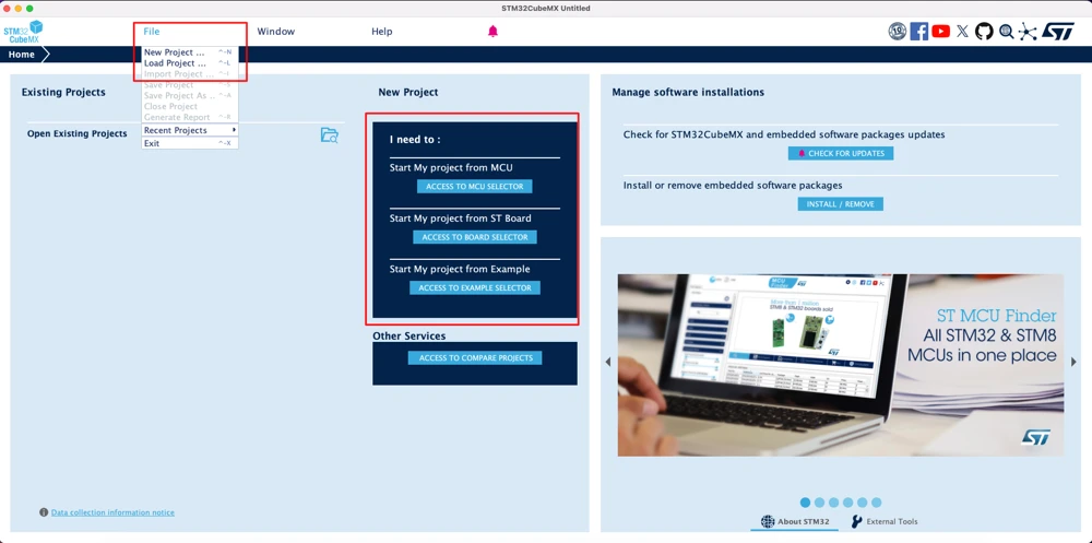
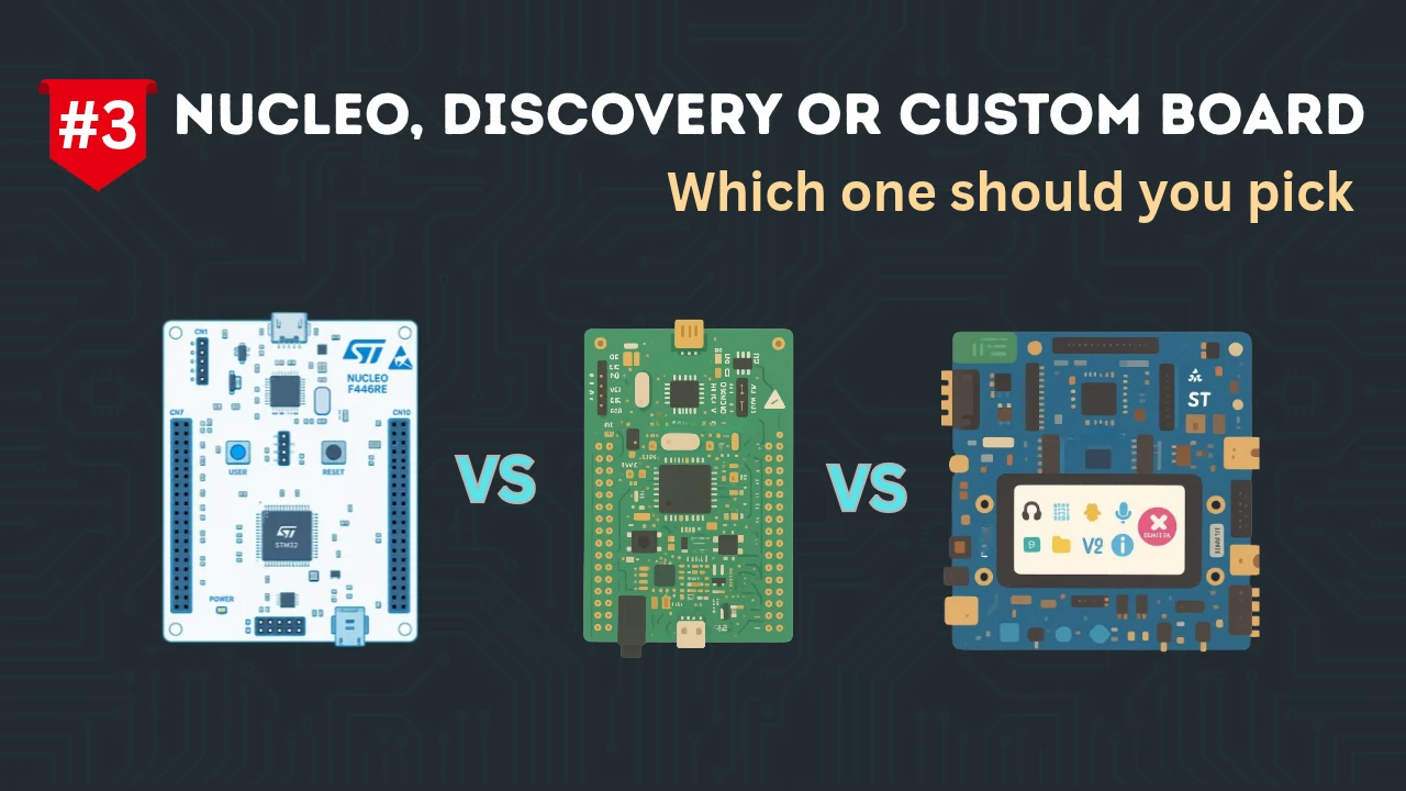
For a new project, you choose “New Project,” and CubeMX opens the selector view, which has two tabs: one for choosing a specific microcontroller part number, and one for choosing a development board. Which tab you use depends on what you are working with. If you are designing your own board or already know the exact part number you plan to use, the MCU tab is the right choice. If you are working with an official development board, such as a Nucleo or a Discovery kit, the board tab is usually faster, because CubeMX already knows the pin assignments used on that board.
Once you select a chip or a board, CubeMX opens the main configuration workspace. This is where most of the setup happens. You will see a few tabs here: Pinout & Configuration, Clock Configuration, and Project Manager. Some versions also have a Tools tab, which includes things like a power consumption calculator. We will cover the important ones in the sections below.
Selecting an STM32 MCU or Board
Choosing the right starting point in the selector view matters, because it determines exactly which peripherals, pins, and memory options will be available to you for the rest of the project.
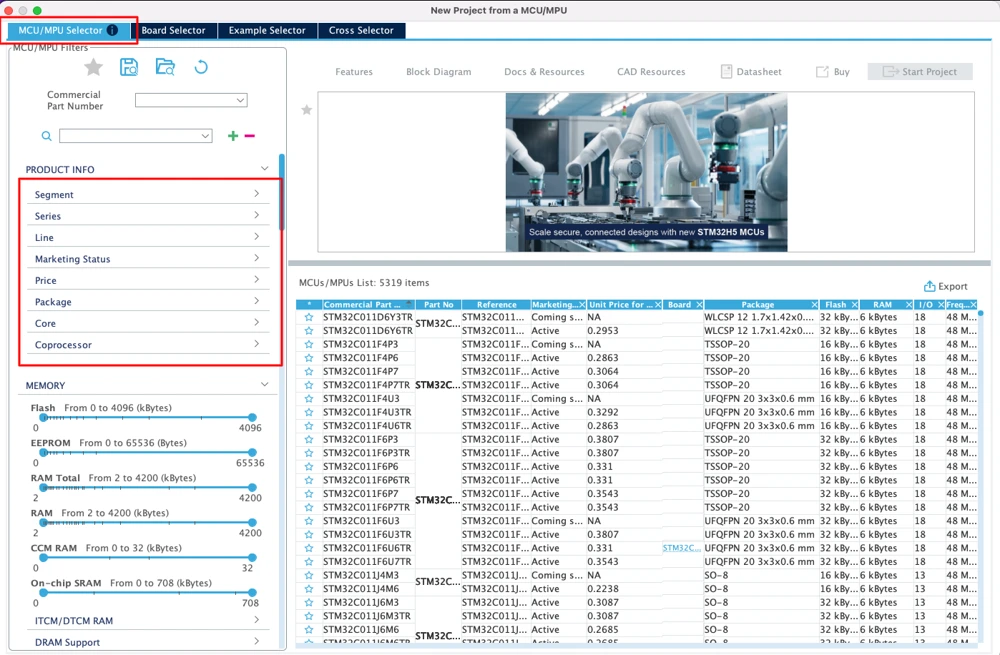
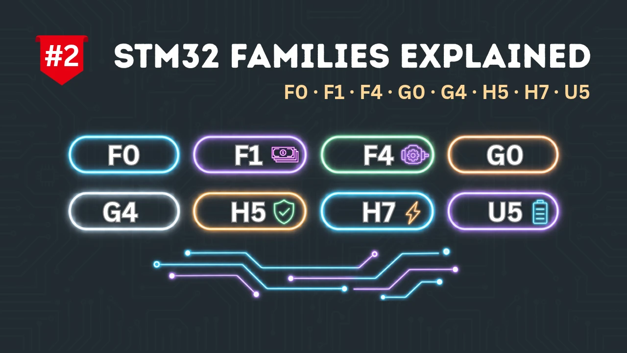
If you use the MCU Selector, you can filter chips by family, by package type, by the amount of flash and RAM you need, and by the specific peripherals your project depends on, such as the number of ADC channels or the presence of USB. This is useful when you are designing new hardware and need to confirm that a candidate chip actually has everything your design requires before you commit to it. The naming convention covered in the earlier guide in this series is directly useful here, since you can often narrow the list down just by knowing the family and series letters you are looking for.
If you use the Board Selector instead, CubeMX shows you a catalogue of official STMicroelectronics boards, including Nucleo, Discovery, and evaluation kits. Selecting a board loads not just the MCU that sits on it, but also the fixed pin assignments for the components built onto that board, such as the user LED, the user button, and the ST-LINK debugger connection. This is the simpler route if you already own a development board, because it means you do not have to work out those pin assignments yourself.
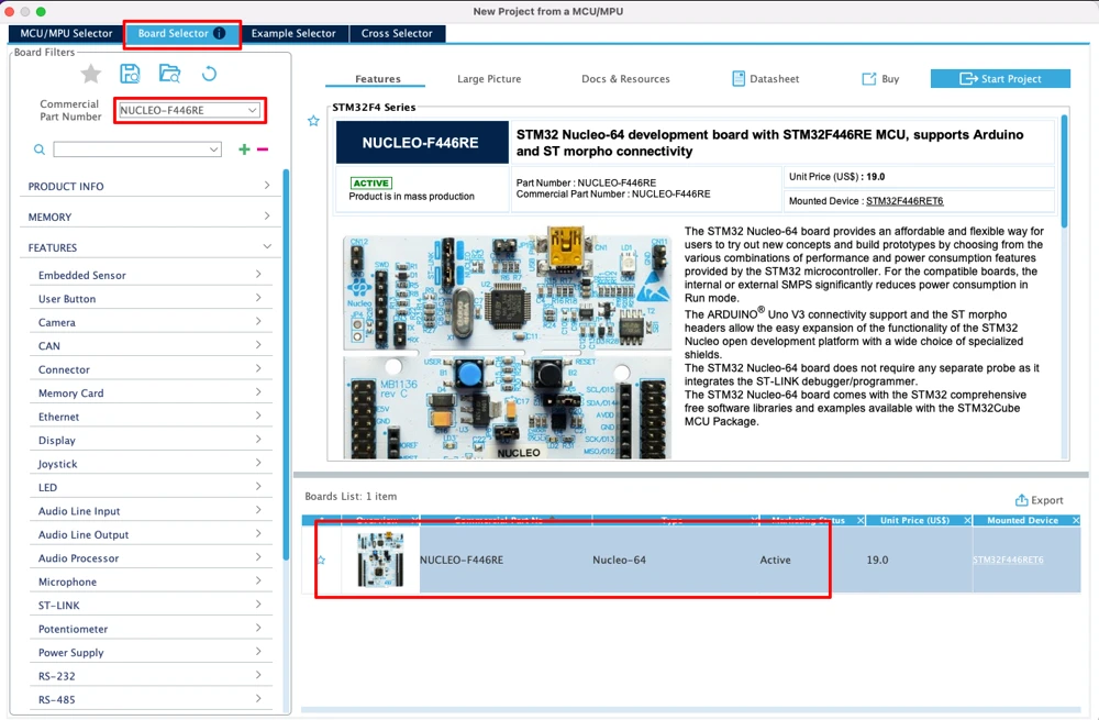
One detail worth knowing is that after selecting the board, CubeMX will ask whether you want it to initialize all peripherals with their default configuration. Saying yes sets up things such as the ST-LINK virtual COM port and the onboard LED automatically, which is convenient for getting a first project running quickly. Saying no gives you a mostly blank slate, which is often better once you already know what your own project needs and do not want extra peripherals enabled that you are not going to use.
Configuring the Pinout
Once you are in the main workspace, the Pinout & Configuration tab shows a diagram of the chip. This is where you decide what each physical pin on the chip is going to do.
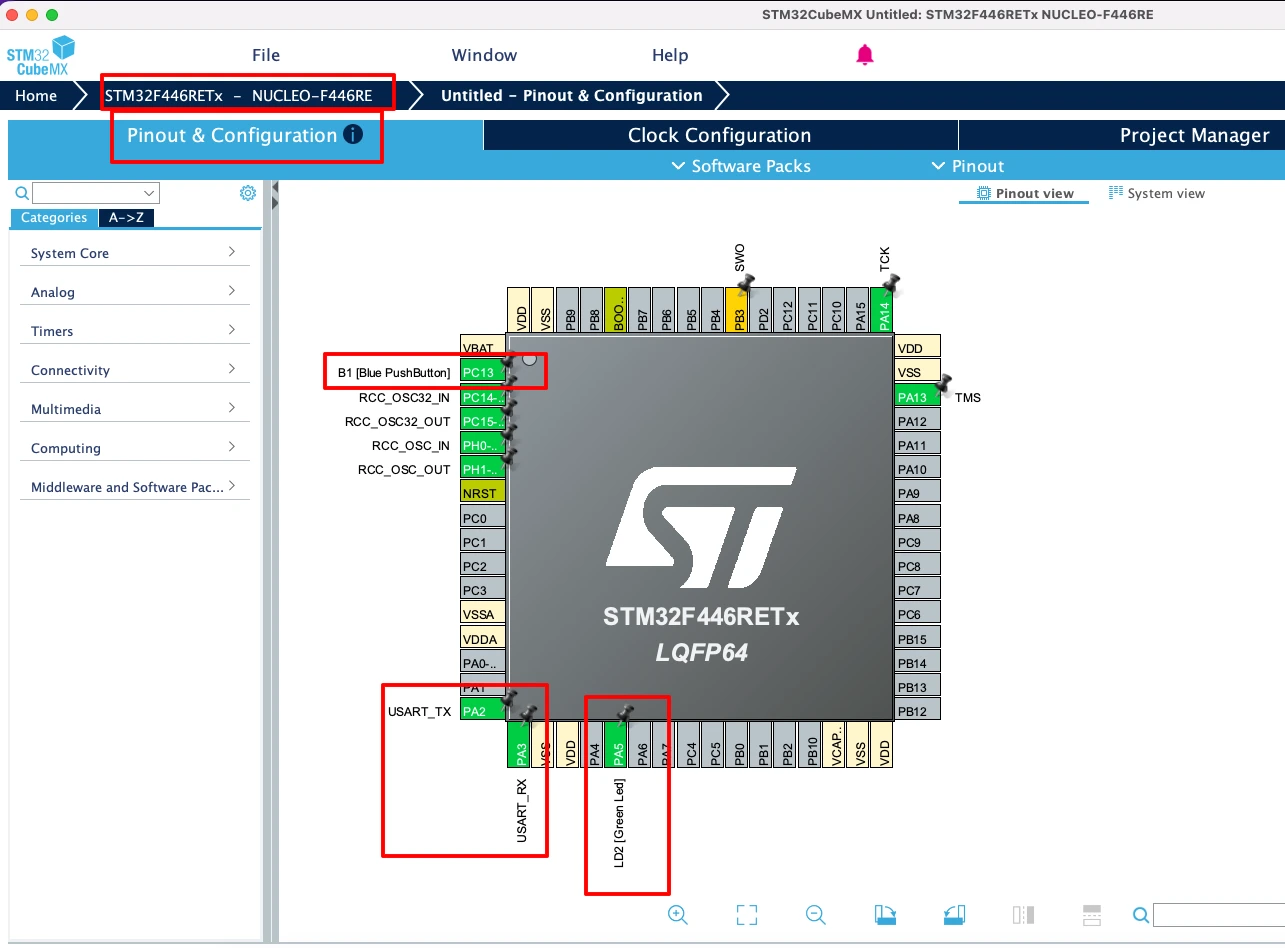
Every pin on an STM32 microcontroller can usually be configured for more than one purpose. A single pin might be capable of acting as a plain digital input or output, or as part of a USART, an SPI bus, a timer channel, or an analogue input, depending on which alternate function you select. CubeMX shows you these options when you click on a pin, and you choose the function that matches what your hardware design needs.
As you assign functions, CubeMX color-codes the pins so you can see their status at a glance. Pins that are unassigned typically appear in one color (Grey), and pins that are assigned to a function appear in another. This immediate visual feedback is one of the most useful parts of the tool, because it catches mistakes early, before you have generated any code or built any hardware around a wrong assignment.
A practical tip here is to keep your actual schematic open next to CubeMX while you configure the pinout. It is easy to assign a pin correctly in CubeMX but forget that the same physical pin is already committed to something else on your board, such as a crystal oscillator input or a boot pin. CubeMX only knows about conflicts between the functions you assign inside the tool. It does not know anything about your external circuit unless you tell it.
For working boards selected through the Board Selector, most of this pinout work is already done for you. In that case, this tab becomes more about reviewing the existing assignments and adding any extra pins your own project needs, rather than starting from a blank chip.
Configuring GPIO and Clocks
After Pinout, the next step is going into more detail on the GPIO settings, the clock tree, and the specific configuration of each peripheral you have enabled.
Setting up GPIO
For a pin configured as a GPIO output, such as an LED pin, you can set details including the output type (push-pull or open-drain), the pull-up or pull-down resistor state, and the output speed.
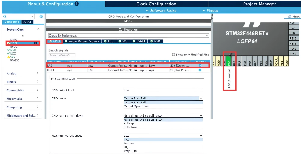
For a GPIO input, such as a button pin, you set the pull configuration and, if needed. You can also set the interrupt mode if you want the pin to trigger an interrupt on a rising or falling edge.
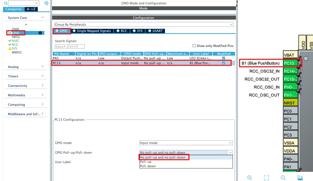
As a working example, I have assigned pin PA5 to a GPIO output connected to the onboard LED, and another pin PC13 to a GPIO input connected to the onboard user button. Leave the output type as push-pull and the pull configuration as no pull for the LED pin, and set the button pin’s pull configuration to match how the button is wired on your board (most Nucleo boards use a pull-down internally on the button circuit, so no internal pull is usually needed).
Configuring the clock tree
The Clock Configuration tab shows a full diagram of the chip’s clock tree, starting from the input oscillator, through the PLL, and out to the buses that feed each group of peripherals. Rather than typing register values, you type the frequency you want at a given point, such as the system clock, and CubeMX works backward to calculate valid PLL settings that will produce it.
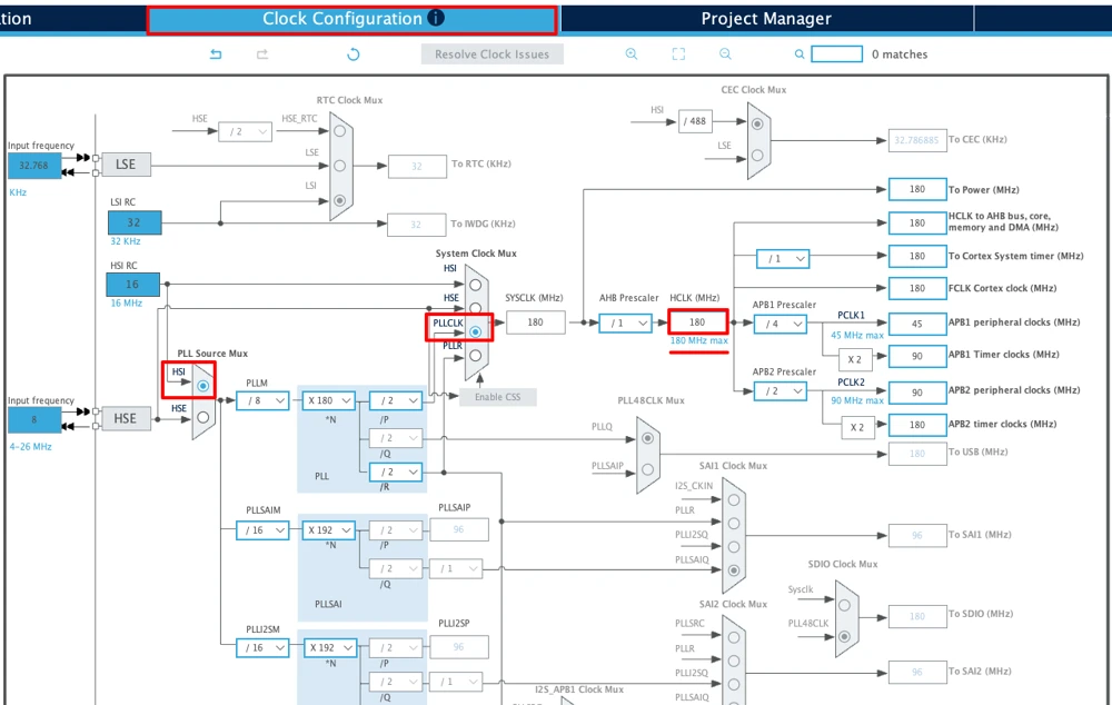
For the working example, set the system clock to run from the internal high-speed oscillator through the PLL, and enter a target system clock frequency, usually the maximum frequency mentioned in the clock tree. CubeMX will fill in the multiplier and divider values automatically and will show the value in red if the combination is not achievable, which makes it straightforward to try a few different target frequencies until you land on one that fits your needs.
Enabling peripherals
Peripherals such as USART, I2C, SPI, ADC, and timers are enabled from a list on the left-hand side of the Pinout & Configuration tab. Turning a peripheral on usually reserves its default pins automatically. If your chip supports it, you can also change these to different pins later.
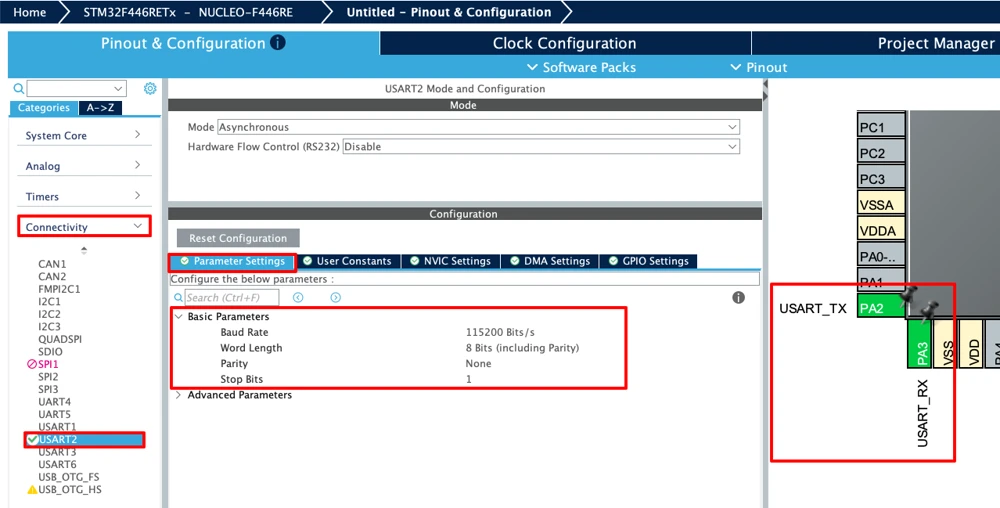
For the working example, I have enabled a USART peripheral in asynchronous mode, and set the baud rate to 115200. This gives the generated project a working serial connection you can use later for debug output, without having to configure the UART registers manually.
Configuring NVIC and DMA
Many projects need more than just basic GPIO and communication peripherals. Interrupts and background data transfers are common needs too, and CubeMX gives you a dedicated screen for setting up each one.
The NVIC (Nested Vectored Interrupt Controller) settings appear on the System Core section of the Pinout & Configuration tab. Here, you can enable the interrupt for a peripheral you have configured, and set its priority relative to other interrupts in the system.
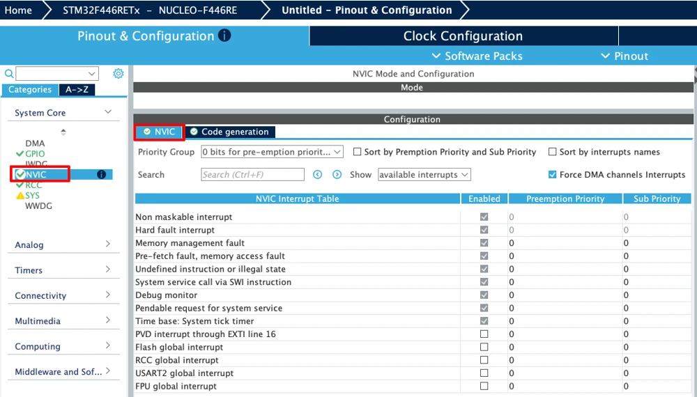
Interrupt priorities matter more than they might first appear. If two interrupts share a priority level incorrectly, or if a lower-priority interrupt is allowed to block a time-critical one, timing problems can show up that are hard to trace back to their cause. CubeMX does not choose sensible priorities for you automatically in every case, so it is worth thinking through which interrupts in your project genuinely need to run first.
DMA (Direct Memory Access) settings have their own section too. You usually get to them from inside a peripheral’s settings, once that peripheral supports DMA transfers. Adding a DMA request lets a peripheral such as an ADC or a USART move data to or from memory without tying up the CPU for every single byte or sample. When you add a DMA request in CubeMX, you choose the direction (memory to peripheral, or peripheral to memory), the DMA channel or stream, and settings such as whether the transfer should repeat in circular mode.

DMA is very useful, but it is also one of the things that trips up new STM32 users. Once CubeMX generates the initialization code, it is easy to forget that DMA is running in the background and doing its own thing. It is a good idea to read through the DMA section of your chip’s reference manual at least once, even though CubeMX handles the configuration screen for you.
Project Manager and Toolchain Settings
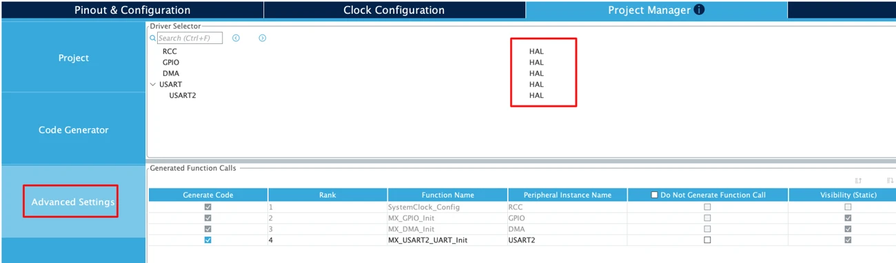
Once the hardware configuration is complete, the Project Manager tab is where you decide how the generated project should be packaged. This tab has three main sections: Project, Code Generator, and Advanced Settings.
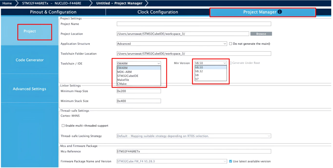
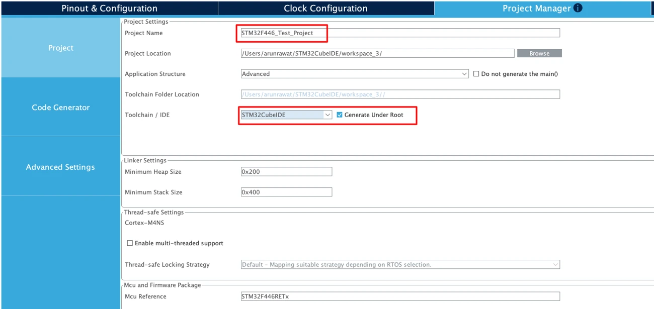
In the Project section, you give the project a name, choose a location to save it on your computer, and select the toolchain or IDE you plan to use. CubeMX supports several options here, including STM32CubeIDE, Keil MDK-ARM, IAR Embedded Workbench, and a plain Makefile output for use with other build systems. Choosing the right option here matters, because it determines the structure of the generated project files and whether they will open directly in your development environment or need extra setup afterward.
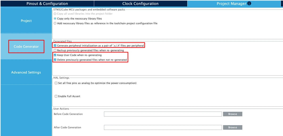
The Code Generator section controls details such as whether CubeMX should generate separate initialization files for each peripheral (generally a good idea, since it keeps the generated main.c file more readable) and whether it should keep any user code you have written between the special comment markers when the project is regenerated later. This second setting matters a lot once you start writing application code inside the generated project, and it is covered in more detail in the section on regenerating code safely, further down this guide.
The Advanced Settings section lets you choose whether to generate HAL driver code or LL driver code for each peripheral individually. HAL code is more portable and easier to read, which makes it the better default for most learners and for most general-purpose projects. LL code is closer to the registers and produces smaller, faster code, which matters more in performance-sensitive or memory-constrained projects. It is possible to mix HAL and LL code for different peripherals within the same project, though doing so adds complexity and is usually only worth it once you have a specific reason.
Understanding the Generated Code
Clicking “Generate Code” produces a complete project folder, structured according to the toolchain you selected in the Project Manager tab. It is worth opening this folder and taking a look through it at least once. This helps you see the connection between what you set up in CubeMX and the code it actually creates.
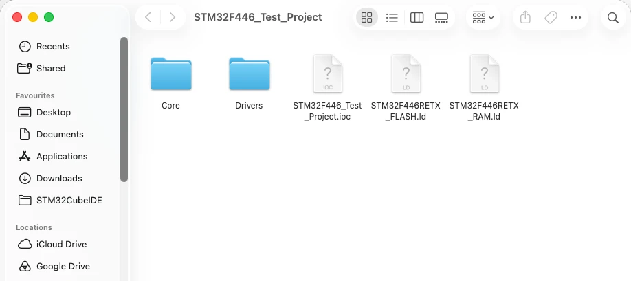
A typical generated project includes a Core folder containing your main.c file along with headers, a Drivers folder containing the HAL or LL library source code CubeMX generated for your chip, and, depending on the toolchain, additional folders for the build system or IDE project files. Inside main.c, you will find a series of function calls near the top, such as SystemClock_Config(), MX_GPIO_Init(), and initialization functions for each peripheral you enabled, such as MX_USART2_UART_Init(). Each of these functions contains the register-level setup that corresponds directly to the choices you made inside CubeMX.
The .ioc file at the root of the project deserves special attention, because it is the actual source of truth for your configuration. This file stores every pin assignment, every clock setting, and every peripheral option you selected, in a plain text format. Double-clicking this file reopens the project inside CubeMX, exactly as you left it, ready for further changes. It is a good habit to keep this file under version control alongside your source code, since it means anyone else working on the project, can see and reproduce the hardware configuration without having to reverse-engineer it from the generated C code.
It helps to go through the generated main.c file from the working example earlier in this guide. You should be able to spot the GPIO setup for the LED and button pins you configured, the clock setup matching the frequency you chose, and the UART setup matching the baud rate you picked. Seeing that direct link between what you configured in CubeMX and the code it produced is really the whole point of using the tool.
Regenerating Code Safely
A detail that catches many people by surprise the first time they use CubeMX is what happens when you go back and change the configuration after you have already started writing application code. Since CubeMX regenerates the initialization files whenever you click “Generate Code,” there is an obvious risk of losing work you have added by hand inside those same files.
CubeMX handles this with a system of comment markers. Throughout the generated code, you will see comment pairs such as:
|
1 2 3 |
/* USER CODE BEGIN 2 */ /* USER CODE END 2 */ |
Any code you write between a matching BEGIN and END pair is preserved the next time you regenerate the project, even if you have changed pin assignments or added new peripherals in CubeMX since the last generation. Code written outside these markers, including anything you add directly into the auto-generated initialization functions, is not preserved and will be overwritten the next time you generate code.
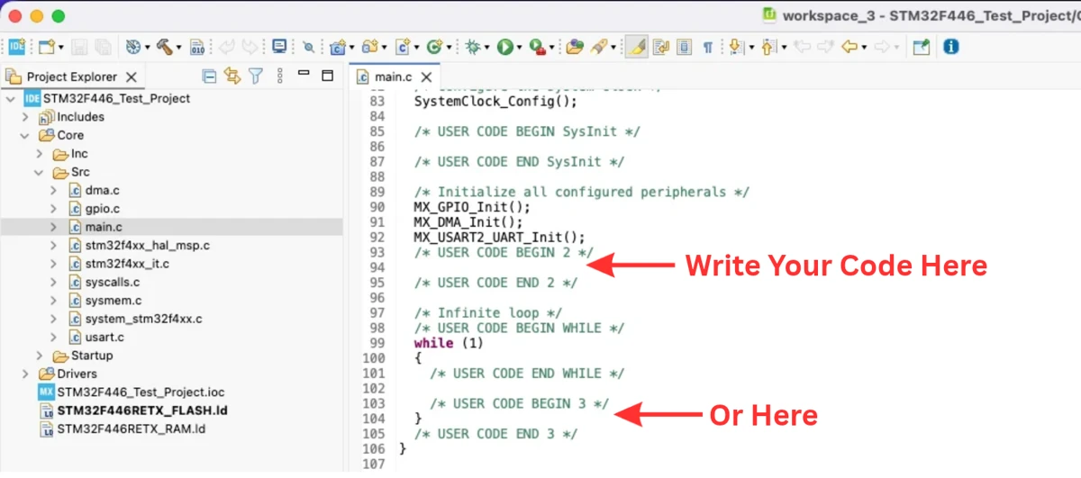
This is the single most important habit to build when working with CubeMX-generated projects. Get into the routine of writing your own logic only inside these marked sections, even for something as small as a single line turning on an LED. It costs nothing to follow this rule, and it saves a real amount of frustration the first time you need to add a new peripheral to a project you have already been developing for a few days.
It is also worth generating code again early and often, rather than doing all of your hardware configuration up front and only generating once. Small, frequent regenerations make it easier to notice if something unexpected changed, and they build the habit of keeping your user code properly contained inside the marked sections from the very start of a project.
Common STM32CubeMX Mistakes
A few mistakes come up repeatedly for people who are new to CubeMX. Knowing about them ahead of time makes them much easier to avoid.
Writing code outside the USER CODE markers. This is the most common mistake, and it usually only becomes obvious the first time a project is regenerated and some carefully written code simply disappears. Always check that your additions sit inside a USER CODE BEGIN and USER CODE END pair.
Enabling peripherals that are not actually needed. It can be tempting to turn on every peripheral that might be useful “just in case.” Doing this adds unnecessary initialization code, reserves pins you may need for something else later, and makes the generated project harder to read. It is better to enable only what the current stage of the project actually requires and add more later as needed.
Not saving the project before making major changes. Because a single .ioc file holds the entire configuration, it is worth saving a copy before making a significant change, such as switching to a different MCU or restructuring the pinout. This gives you an easy way back if the new configuration turns out not to work as expected.
Assuming board defaults match your final hardware. When starting from the Board Selector, it is easy to forget that some default settings are specific to that exact development board and will not necessarily be correct once you move the project onto your own custom hardware. Always double-check pin assignments and clock sources when transitioning a project from a development board to a production design.
Wrapping Up
STM32CubeMX is, for most STM32 projects, the natural starting point. It takes the slow, mistake-prone parts of hardware setup, like pin assignments, clock calculations, and peripheral registers, and turns them into a simple visual process. This is faster and much less likely to go wrong.
That said, CubeMX works best when you understand what it is doing behind the scenes, rather than treating it as a black box. Reading through the generated code, keeping the .ioc file under version control, and respecting the USER CODE markers are all habits that make the tool genuinely useful rather than a source of confusion later in a project.
Download the CubeMX Example Project
Download the CubeMX generated .ioc file.
If you find this useful, you can support us with a Donation as well.